Showing posts with label antennas. Show all posts

Thursday, 29 October 2020

BCB DX + A (Possibly) Quieter Receive Antenna


The earlier very quiet geomagnetic field has produced some amazing propagation on the AM Broadcast Band for west coast DXers. Where local blowtorches don't splatter the band, the past few nights have produced audible signals from several European countries while the mornings are filled with Asians and signals from Alaska ... yes, on the AM Broadcast Band!

The morning of October 11th was particularly good here, with 9 different stations in Alaska heard. Listen and see if you can hear the identification at the top of the hour (7 AM my time):

  780 KNOM  Nome         https://qsl.net/ve7sl/knom.mp3

  670 KDLG Dillingham    https://qsl.net/ve7sl/kdlg.mp3

  700 KBYR Anchorage    https://qsl.net/ve7sl/kbyr.mp3

  680 KBRW Barrow        https://qsl.net/ve7sl/kbrw.mp3

  890 KBBI   Homer         https://qsl.net/ve7sl/kbbi.mp3


This is a short clip from HLAZ, Far East Broadcasting Company, with their 'Radio Liangyou' program in Japanese. HLAZ is located in Jeju, South Korea. They will also respond to reception reports with a nice card ... sadly a growing rarity with AM broadcasters nowadays.


 These were received using my Perseus SDR and 10' x 20' active loop pointed to the NW.

Hopefully these nice conditions will continue for some time but on the other hand, I'd like to see the Sun ramp-up its sunspot production as fast as it can, which would likely put a damper on these quiet conditions. (post edit: and that's exactly what happened!)

*************************************************

An interesting antenna that may help overcome their noise issues is described by KK5JY on his website here. 

It looks simple enough to deploy and try to see if it overcomes your local noise issues. Those with underground utilities however, may find that it makes the noise worse.

courtesy: kk5jy.net


Wednesday, 8 January 2020

PAØRDT Miniwhip Shakedown

The following blog was originally published in January, 2016 but there is still much interest in this popular and well-performing antenna.

           ***********************************

A recent posting to the 'ndblist group' by Mike, an ardent NDB DXer in the UK (Sussex), announced the recent completion of his four-part video series describing the installation and testing of a new PAØRDT active antenna.


If you may be contemplating the installation of an active antenna such as this, or perhaps making a start at DXing the NDB band or listening on 630m, then you might enjoy following Mike's journey as he demonstrates that living in the noisy suburbs need not keep you from enjoying the LF/MF bands. Mike includes some interesting tests involving his grounding system versus noise ingress and the results of keeping the electrical main's ground isolated (or not) from the antenna cable's ground.

The PAØRDT active whip is available from PAØRDT himself or if you are handy with a soldering iron, you might choose to build the same antenna in your workshop. These simple yet highly effective receiving antennas are being used successfully by hundreds of listeners all over the world and for their size provide some pretty amazing performance.


Much more information on the PAØRDT e-probe antenna may be found here in a previous blog posting. To see more of Mike's videos, you can visit his interesting Youtube Channel here.

Wednesday, 28 August 2019

My 10’ x 20’ Active Loop

courtesy: americanradiohistory.com


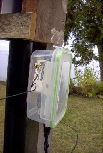
After recently installing a new coax run out to the loop and after five years of summer sunlight, the plastic food-storage container used to house the loop’s preamp (Wellbrook ALA100LN ... LF-30MHz) finally bit the dust ... literally.


Last week I replaced the housing with a slightly larger plastic box but I’ll still be faced with the UV bombardment and eventual deterioration of the clear plastic and lid unless I do something different.


I’ve a couple of thoughts but am hoping for some other suggestions from blog readers.

I have thought about spray painting the container, which may (or may not) prevent UV damage, but wonder if paint will stick to the smooth plastic surface? Maybe if scuffed-up a bit it would stick ... if so, the coating could be annually renewed.

Another idea is to cover it with duct tape ... not pretty, but possibly doing the job. Any other thoughts out there?


Part 2 and Part 3 of this blog were originally published when the loop was first built (2014) and describe the antenna details as well as showing the loop in action ... listening on the NDB and broadcast band as well as showing its nulling capability. It’s been a great performer and  I can highly recommend the ALA100LN for a large aperture receiving loop. I’m looking forward to what will hopefully be a good winter of exciting loop DXing.

Part 2 - New LF / MF Loop


Some may recall my blog back in July (Wellbrook Loop Plans) describing a new loop that I had been thinking about as a possible replacement for my 10' shielded loop. I had been doodling various construction ideas using PVC tubing in an effort to keep it as light as possible, without introducing any metal near the loop. On Monday of this week, I dismantled the 10' loop in preparation for my new experimental rectangular loop.
I've had the Wellbrook loop preamp here for a few months, so it was now or never, while the weather was still 'antenna-friendly'. Now I do understand that this goes against one of ham radio's long-standing traditions that dictates all antenna work must wait until the weather can't get any worse. Antennas built in the winter rain always work much better than ones put up in the summer. Hopefully it's not Wouff-Hong or Rettysnitch punishable but the fall DX season is almost upon us and I'm not waiting for the rain!

The new 'loop' is not really loop-shaped but is rectangular (10' x 20') and more like a Flag antenna shape. I considered a Flag but really don't need any back-end nulling capability since I'm mainly interested in listening to the east and to the north.


The main boom section is composed of two sections of 1" PVC thick-wall (Schedule 40) pipe joined at the center and reinforced with a 10' section of 2" x 2" Douglas Fir. In addition, the boom has a truss of 1/4" Dacron to take out any end-loading sag. The vertical end sections are 3/4" Schedule 40 PVC pipe, fastened with a T at the boom end. The center mast is made of 2" Schedule 40 ABS pipe with a long section of 1 1/2" ABS nested inside that telescopes upward to anchor the truss ropes and give some additional rigidity to the mast.


Main boom and mast construction
This type of construction would lend itself well to anyone interested in a rotating Flag antenna for the BCB / LF or 160m. The costs are very low, the structure is lightweight and the materials are readily available at most hardware outlets.


Looping E/W


Although the preamp is completely sealed and weatherproofed, I still decided to mount it inside a container. The container also provided a convenient anchor to terminate the loop end wires (PVC-coated #18 stranded) without putting any tension on the soldered terminals.

Although I have not had much time to listen, and conditions are still in 'recovery' mode from earlier disturbances, initial indications are that everything is performing as well, if not better, than expected. It certainly outperforms my 10' active shielded loop by a large margin. I have yet to do any serious S/N comparisons between it and my primary LF receive antenna, a large inverted L, which must be tuned to resonance for the desired listening range. I believe that the very quiet loop / Wellbrook combination will provide an overall S/N improvement.

I have always believed that smaller loops provide deeper and sharper front-to-side nulls so I was pleasantly surprised to measure (using Perseus) null depths from 25-30db, on various groundwave signals ... more than expected. Skywave signals also deliver sharp deep nulls in the order of 22 - 25db ... again surprising, but I'll take them!

A brief listen while pointing S-E last evening turned up good signals from 1 kW'ers KYHN (1650kHz) in Fort Smith, Arkansas and KKGM (1630kHz) in Fort Worth, Texas. An early morning listen revealed good audio from JOIK (567kHz) Sapporo, Japan and JOAK (595kHz) in Shobu. Down in the ndb band, little 25-watter 'IP' on 210kHz was an all-time new catch from Mobile, Arizona.

There is still much to learn from this new antenna system but the biggest challenge will be keeping it up all winter. I did lose one of my 10' loops after several years, due to wind, when the main (un-reinforced) PVC mast eventually failed from flexing fatigue. I will tie the ends of the new antenna down when the winds get strong to reduce as much mast flexing as possible. I could however, run the risk of violating another long-standing radio adage ..."if your antenna stays up all winter, it's not big enough". I just can't win.

Part 3 - Loop Listen 


As Murphy would have it, and in spite of the low amount of solar activity, LF/MF propagation has been very poor since getting my new 10' x 20' loop in place. The few front-to-side nulling checks that I have done, have produced results varying from around 20db to 30db, depending upon the signal. I suspect the depth of null is also affected by the signal's arrival angle but there is still more to learn. The pattern seems to be very close to that of a typical circular loop...the classic figure-8 pattern illustrated below as shown on the Wellbrook data that came with my ALA100LN preamp.

Courtesy: http://www.wellbrook.uk.com

More typically, the null is around 21-22 db as shown on this test while listening to the ground wave carrier of the 'YZA' NDB (236kHz) located in Ashcroft, B.C., about 150 miles to the NE. As expected, the null is fairly sharp and the front / rear lobe, fairly broad.


One short check at dusk produced nice signals from  CJBC, the French-language station in Toronto. The past few nights it has been very strong but with a strong echo effect. I wonder if there is more than one CBC outlet here (860kHz), such as a low-power repeater, causing the echo.


At the same time, while still fairly light outside, WCCO in Minneapolis had a nice signal just before sunset.


No matter how poor conditions become, it seems that the Hinchinbrook (Alaska) NDB, 'ALJ' (233kHz), is always strong ... looping north.


Courtesy: https://www.google.ca/maps
My apologies for the video quality. If you know of any software available for making full-screen Perseus video captures so that I might improve my technique, please let me know. Presently I am just capturing them on my I-Pad which leaves a lot of room for improvement.

(Since originally posting the above, I have been using the Tiny Take free screen capturing software, to produce better quality catures of my Perseus recordings. It's also probable that my new iPhone would produce a high quality video of my computer screen compared to the older iPad used for these ones, but it's something yet to be tried.)

Hopefully conditions will only get better as the season progresses and I am able to give the loop a good workout ... before it gets too windy!

Friday, 5 April 2019

My End-Fed Half-Wave (EFHW)

The last few years have seen a resurgence of interest in the end fed half-wave wire EFHW antenna. A half-wave at the lowest band of interest will also work well on all harmonically-related bands which has become particularly attractive to those wanting a quick portable wire antenna.

It looked like an interesting antenna to try, as I was in need of a good 80m radiator and following several days of fine summer-like weather, I was able to get my new 80 / 40m wire vertical completed ... a half-wave on 80 and a full-wave on 40m. It’s built as an inverted-L, going up 80’ and the remaining 50’ being horizontal at the same height. It’s fed at the base through an impedance matching transformer and was pruned for the CW end of the band.

There's always a great sense of anticipation when first testing a new antenna and the experience only comes around once in a rare while ... it always brings back memories of my teenaged ham years, quickly scrambling off of my parent's steep three-story roof and tuning-up the DX-20 to see if the latest antenna was going to be something special. Yesterday was similar, except for the roof-top scrambling and the old DX-20.

By mid-afternoon everything was wired up ... but before waterproofing all the connections against the west coast rains, I went to the shack and warmed-up the FT-1000mp, setting it for exactly 10W out. Tuning across 40m, I immediately heard fellow NRR’r Howie, WB2AWQ down in Reno, calling CQ on 40m with one of his military transmitters. He came back immediately and we had a short chat, so at least I knew the new antenna worked!


Having  waterproofed all of the connections, I ventured to the shack once more, now just 45 minutes before sunset. I’ve always found that a quick way to gauge relative antenna performance is listening for my low-power signal via the vast KIWI online SDR network

With the power still set at 10W on 40m I listened on several east coast SDRs, from NH, PA, MD, NY, VA and immediately heard a surprisingly good signals on all of them. Even at 5 W, the signal was copyable. Several of them produced an audible copy when I reduced power to just 1W.

I then tried two SDRs in Brazil and immediately heard the 10W signal again! How about KH6 ... still late afternoon out there? Yes, easy copy in Hawaii as well. 

Dare I push my luck and try one more ... one of the SDRs in Iceland? 

I almost fell out of the chair when the 10W signal was good copy there as well ... still 15 minutes until sunset and with bright sky outside the shack window. 

One last thing to try was 80m although it was still very early here for 80 ... the SDR in MD returned a nice copy at 10W to complete my quick round of pre-sunset testing. 

From these early observations it would appear that the new antenna is working well but I had yet to do any A-B comparisons with my benchmark best performer, a 40m half-sloper which will be hard to beat. 

The 40m half-sloper has always outperformed any other antennas that I have tried. It's the same one that I completed my Tuna Tin 40m W.A.S. on, so its been well tested.

The following evening, I had a chance to A-B test the new antenna, listening on the Kiwi network once again with my power set at 10W.

N8DTT/6 (California)  EFW 1S unit better
NO2CW (Florida)   EFW slightly better
Jersey Shores, NJ    EFW slightly better
TF1VHF (Iceland)  EFW slightly better
ND7M (Nevada)     equal with slight edge to EFW
KA7EZO (Utah)      equal
RTM (Dominican Republic)   sloper ~ 1/2 S unit better
KP4CA (Puerto Rico)   equal
Paraguay   equal
PY2GN (Brazil)   EFW ~ 1/2 S unit better
AI6VN/KH6 (Hawaii)   equal
VE7HUN (BC)   equal  (groundwave)

Unlike 1/4 wave verticals that require a fairly robust counterpoise / radial system for effective operation, the counterpoise requirements for a half-wave are far less-demanding. Mine consists of about fifteen short turf-pinned radials and the first 50' of the coaxial feedline's shield. A common mode choke (CMC) is installed on the feeder at the 50' point, keeping any RF out of the shack and the rest of the feedline from radiating.

I was actually pretty surprised at these results but how they will relate to everyday operating is yet to be determined. My main goal was to get a good-performing 80m antenna and anything that works well on 40 would be a nice side benefit but not really required. Unfortunately I don't have another 80m antenna to run some A-B checks with but from what I can tell, performance on 80m seems to be good.

If you are on Facebook, there is a lot of good discussion and information available on the End Fed Half Wave Antennas group.

Thursday, 12 July 2018

My New 80 / 40m Antenna

80 / 40m wire vertical groundplanes, now removed


For the past several years I have employed wire vertical groundplane antennas for both 80 and 40m, mounted a few feet from the ocean.


In the fall I layout the ground radials on the grass and in the spring, roll all of them up again. The main reason for going to the vertical was to eliminate problems with my 80 / 40m half-slopers when using my 1929 single tube power oscillators during the windy conditions usually encountered during the mid-winter '29 BK QSO Party.

The flexing between the tower's telescoping mast sections and the Yagi antennas that form part of the sloper's 'top hat' , cause the half-sloper's impedance or resonance to change ever so slightly. The directly-coupled oscillators respond to these minute antenna changes by constantly shifting frequency by several hundred Hertz, as their output load changes. These high winds can make the low-power oscillator difficult to copy under weak signal conditions as it suddenly jumps frequency. The verticals were immune to this 'wind effect' and performed very well ... sort of.

I've noticed, over the years, that the verticals seemed to produce a much better signal out on the eastern edges of the continent than they do in the central states and in the closer western (PNW) states. I decided to see if an inverted-V might produce a higher takeoff angle and give me a better signal in mid-continent and an 'OK' one on the east coast. The half-slopers on the other hand, always seem to produce a good signal both near and far, but could usually not be used with the one-tube power oscillators when it was windy ... which, during winter here on the coast, is a lot of the time!

Following the removal of the old wire verticals and several days of antenna building, the new 80 / 40m dual inverted-Vs were hoisted to the top of my 85' Balsam. After pruning for resonance, I have been able to run some comparisons between the 40m V and my present 40m half-sloper. The 80m half-sloper had already been decommissioned as it required the changing of a jumper to use and I was never able to resonate it properly for some reason. Oddly there was no problem with either the 40m or 160m half slopers, fed at the same point, as both resonated easily.

The new 80 / 40m dual inverted-V dipoles

The dual dipoles, both resonated to the CW portion of each band, are separated every 10' by 24" varnished and painted hardwood spreaders.


The old 40m sloper has always been a really great performing antenna (except for the power oscillator / mast flexing problem) and it was the one used for my 300mW Tuna Tin Worked All States, back in the fall of 2000. I've had good success with both the 40m version and the 160m version, with 159 countries now confirmed on topband using the diminutive 130' wire.


The 'Half-Sloper' was given a close analysis by antenna guru Jack Belrose, VE2CV, and described in QST of May, 1980. In his article, "The Half Sloper - Successful Deployment is an Enigma", he found that the radiation pattern was almost identical to that of a top-loaded monopole, fed against ground. The radiation field was largely vertically polarized and omni-directional while a lesser component, about 10db down, was horizontally polarized and coming from the sloping wire. The horizontal component had a figure-eight radiation pattern, slightly favoring the direction of the wire. He suggests that this antenna should be avoided due to the difficulty in getting it properly tuned.

My own experience with half-slopers have been mostly very positive, in spite of the tuning problems with the 80m version. To me, it seems like an ideal low band antenna for the small backyard, if you can get it to tune correctly. Assuming you already have a tower with some beams to add top-loading, hanging half slopers for the low bands takes up very little space. With omni-directional low angle radiation along with some higher angle horizontal radiation, all in a small footprint, what could be better for a simple wire antenna? Well, hopefully, my new high inverted-V!

For the past couple of weeks, as described earlier, I have been comparing the new 40m inverted-V against my 40m half-sloper, 'A-B' style, in real time, using the KiwiSDR network of online receivers. It seems that about 75% of the time, my old half-sloper, is just a few db better than the new V ... after all of the work involved, these results were both surprising and somewhat disappointing!

Perhaps I shouldn't be surprised after all, since the inverted-V configuration for a dipole is certainly less than ideal and the included angle in my antenna's normal position is only about 90 degrees. As well, the feedline attenuation losses for the new antenna are about 1db higher than those of the sloper. During the winter, I will be able to move one leg over to the far side of my neighbour's property which will open the apex up to a full 180 degrees. Recent testing at this angle has made the antennas neck and neck with one beating the other about 50% of the time, but the inverted-V is always better to the closer states.

Unfortunately, I have nothing to compare the new 80m antenna against but from listening to the signal on various SDR's around the continent and into the Caribbean, I have every confidence in it providing a much better signal than I have previously been able to muster on that band ... it should really help during the '29 BK QSO Party and the next NRR CW Party.

So what has been accomplished with the new installation? I have gained what appears to be a very good performer on 80m, as well as a 40m antenna that seems to be as good as the known good performing half-sloper, and should not cause any frequency-hopping with the one-tube power oscillators. My signal into the nearby PNW and central states has been improved. As well, now I can also avoid the annual radial deployment and retrieval needed for the wire verticals.

I'm still testing both antennas but conditions have been less than co-operative over the past few weeks. Hopefully when propagation picks up again, some of the European and far out Pacific SDRs can be used to further compare the two antennas ... there may yet be more to come!

Saturday, 16 June 2018

An Online Alternative For Comparing Antenna Performance


Over the past few years, the Reverse Beacon Network (RBN) has been utilized by thousands of amateurs to gauge the performance of their antenna systems, to check propagation or to compare their station's antenna performance against another nearby amateur's system.


For those not familiar with the RBN, it is the opposite of a network of 'on-air beacons' and consists of a network of 'on-air receivers', usually SDRs, that automatically skim a wide range of frequencies within the CW bands and report back what they hear, along with a definitive signal strength report ... all posted immediately back to a central website where you can read the data from the various stations that have heard your signal. Calling 'CQ' or sending a few 'TEST de' signals, followed by your call sign, will trigger the desired network response.

I have recently been testing a new 40m antenna, an inverted-V dipole at 80', against my long-used half-sloper, but have been using a different online receiver network to make my real-time comparisons ... the KiwiSDR receivers, mentioned in previous blogs. I'll have more to report about the new antenna and its performance in an upcoming blog, once everything is finished and the antenna is fully optimized.


When it comes to real-time 'A-B' antenna comparisons, I found the KiwiSDR network much more interesting and informative than using the RBN. If hard data is what you want, then the RBN will provide it, but not in the same real-time, 'A-B' style that the Kiwis can offer. Once set up so that the two antennas may be fast switched, 'A-B' style, you can actually hear the difference immediately, with your own ears, as if sitting at the online receiver hundreds or even thousands of miles away. By sending a continuous series of dashes while switching between antennas, the comparison can be strikingly obvious, as the propagation variances experienced in an RBN comparison are no longer a factor. One might argue that using longer RBN comparisons, averaging the signal strength over a period of minutes, may yield a truer picture of antenna performance ... but this method lets you hear the second-by-second differences as they happen.
 
My antenna testing is not yet complete, as much of the initial time was spent trying to determine which online receivers were suitably quiet enough to utilize. Many of them were rejected for being far too noisy to be useful while many others were found to be ideally quiet. I am slowly working my way through the list!

So far, I have been able to listen to my transmitted signal and compare the two 40m antennas on numerous receivers from coast to coast, both near and far, as well as into the Caribbean and South America. I have found the best power to use is between 1 and 5 watts, as making the signal intentionally weak at the receiver end makes subtle differences of just a few db easier to detect.

The gathering comparisons are fascinating as often the signal strengths between my two antennas are very different. Often the sloper and the inverted-V are neck and neck, while in different directions or at different distances, one or the other is a clear winner. On many far-off receivers, I was easily able to detect my signal with all power controls set to '0' with no indication of any output showing on my meters, a rather surprising observation and another reminder of how RF just loves to radiate ... even at very low levels!

If you want to try this yourself and can quickly switch antennas 'A-B' style, here are the direct links to a few of the receivers that I have found to work very well so far ... with low noise levels and no man-made crud, while listening on 40m.

KA7U SDR - Idaho

K1RA/KW4VA - Virginia

W0AY - Montana

K2SDR - New Jersey

G8JNJ - England

K2ZN - New York

WA2ZKD - New York 

KD4HSO - Kansas

VE6JY - Alberta

W3SWL - Pennsylvania

N6GN - Colorado

N8DTT/6 - California

VE6JW - Alberta 

Kingwood - Texas

TWR - Bonaire

EA8DGL - Canary Islands

Wellbrook ALA1530LNP - Southern Finland

NO2CW - Florida

Pardinho - Brazil

I will continue to update this list as more receivers are tested ... now back to some outdoor antenna tweeking!


Thursday, 7 June 2018

Trouble Free HF Antenna For The Apartment Dwelling Ham

Unfortunately we all know of or hear about hams that have given up all hope of getting on the air, once moving into an apartment or condo, where antennas are normally prohibited. One enterprising local amateur has combined early established antenna fundamentals along with sound engineering, to arrive at an elegant and highly successful solution. If you are also a 'location challenged' amateur, it may just be the thing that will help you, and others, take back your hobby and get on the air!

John, VE7AOV, has been operating from his apartment, in the heart of the very large and noisy greater Vancouver, for several years now ... not simply 'operating', but thriving, from his cozy fourth-floor apartment radio station. The wallpaper shown below would not usually be expected to grace the shack walls where antennas are not permitted!


It's soon apparent that John has also overcome the usual problem of noise ingression, from every appliance and random RFI generator in the complex. This is no lucky fluke but all by design, and delivered via an all but invisible classic antenna system made of #26 wire and a few Starbuck's stir-sticks!

600 ohm #26 balanced line

I'll let John tell you a bit more before sending you to his fascinating website, Intuitive Electronics, where you can learn more about his system and the engineering behind his successful, low-noise installation.

When it comes to a high frequency ham station, the antenna alternative chosen by most apartment dwellers is no antenna at all. The design here is a wisp of an antenna that bothers no one and which can work Japan, Australia, France, European and Asian Russia, the Caribbean, Central America, Polynesia and South America from the Pacific coast of Canada. It is a simple solution for apartment dwellers, it is a cheap solution and it causes no t.v.i. or other r.f. problems. It is far preferable to the alternative selected by so many fellow apartment dwellers: no antenna at all.

An implication that it seems to be impossible to rid from the minds of fellows using a Marconi antenna is that they are not just pumping 100 watts of r.f. into their antenna but that they are also pumping that same 100 watts of r.f. into their ground, that is to say the building’s wiring, the safety ground wiring. R.f. in the safety ground is well coupled into the power and neutral conductors of a residence and, in North American code, is even hard connected to the neutral line at the service entrance. The house wiring becomes part of the antenna system.

The ground wiring and everything connected to it is every bit as much a part of the antenna as is the live element. Both radiate just the same amount of r.f. power, fellows. The ground wiring along with every electrical power consumer in the building is worked against the live element. Thinking of what is connected to ground in your house is thinking about one side of your antenna. It’s not just appliances that get the “benefit” of r.f. The land line telephone system, the cable television system, the garage door opener, the security lights and…you name it. They are all “feeling” that 100W of r.f. With regard to r.f., there is no distinction whatsoever to be made between “hot” and “ground”.

You know the reason why vertical antennas have gained a reputation for being noisy on receive now, too. Most verticals are Marconi antennas. Both the safety ground and the neutral serve all the houses in the neighbourhood. The receiver is wired into the electrical appliances of the entire neighbourhood.

This radio station, located four stories above grade and in a wooden building full of apartments would be a worst case for r.f. in “ground”. This station has no r.f. in the station. It has no r.f. in “ground”.

The station has no interference issues. The Building Manager, the Building Superintendent and the administrator for this building’s cablevision have been aware of the station from the beginning. There has not been a single complaint of t.v.i. or any other complaint about the station. That’s a clean record extending back to 2006. There are no red faced, spluttering tenants hammering on the door of this station! At this station, all the r.f. produced by the transmitter makes its appearance out on the an­tenna. The radio station’s r.f. is not referenced to station ground. Station ground “knows nothing” about the r.f. being generated.

In the present case, that is to say a station to be operated in an apartment building, it is required to have an antenna that is “invisible”. Now it’s not possible to achieve that literally but at least the antenna should be so inconsiderable that there will be no complaints from neighbours about having to look at it. The antenna here is made of #26 A.W.G. wire. That’s wire that is 0.40mm, 0.016 of an inch, in diameter. Four stories up, it’s difficult to see the antenna and that’s even when knowing where to look for it. Part of the antenna’s run is through trees and in among the tree branches it pretty much is invisible. It does not annoy neighbours by casting a shadow; there is no shadow.

In spite if the naysayers, John's small gauge antenna has survived years of winter storms, regular occurrences here on Canada's western edge ... simply because it presents such a low cross-section compared to most conventional antenna wires.

To read more about enjoying your hobby again from your new 'restricted' location and more than likely, learn something new about old fundamentals, give John's website a very close inspection ... there is much wisdom and many gems to be found, even if you don't live in an apartment!

Thursday, 1 March 2018

Condo Hamming, The NRR and Ron's Logs

courtesy: K4VRC Group
An interesting thread has developed recently on the e-ham.net reflector concerning the enjoyment of your radio hobby from a condo / townhouse or similar sites subjected to the typical 'no outside antenna' rules.

Rick, KB2NAT, describes the learning curve in his 'How To Overcome Some Condo Issues' post.

Amateurs contemplating downsizing to a restricted development or those finding themselves in a similar situation to Rick will likely soon be subjected to more noise, less space, more neighbours and an abundance of rules. Hopefully the comments of Rick and others will be helpful if this is your situation.

For many restricted hams, Mag loops appear to be a popular choice and one of the comments points to a good deal of information on building one for yourself. The Villages Amateur Radio Club (K4VRC)  group's 'resources' link will provide some interesting ideas for restricted antenna builders. As well, they have put together an informational presentation, full of great antenna ideas for those contemplating ways to get on the air from antenna-restricted locations.

If you live in the USA, the 'Freedom to Display the American Flag Act of 2005' has been used by many antenna-restricted hams, to legally erect their own 'antenna flagpole'! It may be an easy route for a nice antenna system for you as well.


The 'Novice Rig Roundup' Starts Tomorrow!


Just a reminder that 9 days of CW operating fun begins tomorrow afternoon. After last year's most enjoyable event, the NRR is now one of my 'must do' operating activities. You can read all about it here.


Ron's Logs


courtesy: California State Parks
If you have any interest in tuning around the international shortwave bands or perhaps are wondering what can be heard there, the daily logs of several dedicated listeners can be found in the Groups.io World of Radio as well as in Yahoo's DXLD group. I particularly enjoy the information posted in 'Ron's Logs' and marvel at some of the DX that he hears each morning from his car!


Ron lives in the seaside city of Monterey (CA) and on most mornings he makes the short pre-dawn drive to Asilomar State Beach (CA), a spectacular location on the coast.


After stringing out his 100' wire antenna on the nearby fence posts, Ron proceeds to log and record some truly exotic stuff before heading home.

Early last Fall, before being aware of Ron's daily regime, I had visited his exact location and after watching the big sea lions playing in the surf, had drooled over the location's great DX potential, little knowing that Ron had likely packed his gear up and headed home just a few hours before my arrival! I'm sure you'll be inspired to tune around the SW broadcast bands after checking out these Group's daily posts.

Monday, 11 December 2017

The FA-VA4 Vector Antenna Analyzer (LF-100MHz)


For some time I had been considering the purchase of the MFJ259 antenna analyzer but after a little online sleuthing, came across this little beauty, the FA-VA4 Antenna Analyzer by Funk Amateur in Germany and available through their Box73 website here.


I liked the fact that the cost of the analyzer was about half that of anything else comparable ($140 US including shipping) and that it covered the new 2200 / 630m bands!

I think many amateurs planning on building a system for either of these new bands will find the very affordable FA-VA4 a handy piece of equipment when it comes to working on their LF / MF antenna since most available SWR meters do not cover these frequencies accurately.

Delivery time was fast and everything was very well packaged. The FA-VA4 comes in partial kit form and requires only a short amount of time to put together.


The necessary assembly consists of soldering pin strip connectors, switches, AA cell holders, and the BNC connector. All of the tricky SMD components have been pre-mounted ... total assembly time was less than 60 minutes and everything fired-up nicely, without problems, thanks to the well written instruction / user manual.


Included with the kit are three BNC connectors needed to calibrate the instrument for the highest accuracy. These consist of a 'Shorted' connector, an 'Open' connector and a 50 ohm 'Load' connector (SOL). A simple three-part calibration procedure for all frequencies takes about 15 minute to complete, while the instrument calibrates itself as it scans through all frequency ranges with each connector plugged into the output. Once this task is completed, the analyzer is ready for use.


If you're like me, I think the main use will be to check out and tweak some of your HF antennas using the SWR or Z sweep function. This allows you to set a desired 'center' frequency along with a + / - sweep range and have the display draw a nice plot of your system.

Had my 630m antenna not already been tuned and matched, I would have found the analyzer to be a great help but, thanks to my 'scopematch', that antenna has already been optimised.

All menu features and data entry is via three momentary-contact push switches. Although this might initially seem awkward, it is not, and operation is pretty intuitive.

The main modes of operation are:

Single Frequency SWR  Measurement

courtesy: http://www.box73.com/product/5

Single Frequency Impedance Measurement

courtesy: http://www.box73.com/product/5

Single SWR Measurement Run

courtesy: http://www.box73.com/product/5

Single Run For Impedance Measurement (Resistance and Reactance)

courtesy: http://www.box73.com/product/5

SWR Measurement On Five Frequencies (5 Band Measurement)

courtesy: http://www.box73.com/product/5

As well, all of the above can be viewed in a continuous 'cycle' mode, as inputs are changed and all screens can be saved for future reference.

Additional capabilities include use in an HF Signal Generator Mode (~ 1V square wave @50 ohms), the ability to measure C and L at a given frequency, as a 'dip meter' and to measure cable resonances and determine lengths.

The complete manual may also be downloaded from their website here.

I will soon put all of my antennas to the test and see what work might need to be done to optimize them, particularly my HF half slopers, which, in spite of their great performance, have always proven a bit of a mystery when it comes to pruning them to resonance ... I rather suspect that the sloping wires are more of an impedance tuning stub than a radiator and that most radiation comes from the vertical support tower, not the sloping wire.

All-in-all, the FA-VA4 appears to offer very good value for the money and is a well built, quality test instrument. I think it will become a popular choice among hams, especially those on LF / MF. The only thing different that I would have liked, would be to have a UHF (SO 239) connector rather than a BNC on the output, since most amateurs are using these on their HF systems ... or, the inclusion of a BNC-to-UHF adapter.

If you already use this device, please feel free to add your comments below!

Thursday, 27 April 2017

LF / MF Antenna Planning

courtesy: Chuck Roblin

For U.S. amateurs, the 2200 and 630m bands will soon be a reality and I have no doubt that there will be an accompanying surge in interest among large numbers of homebrewers and low band diehards.


It should be an exciting time as new stations gradually start to populate the band from coast to coast.

High on the 'to do' list will be the planning and building (or modifying) of a suitable antenna system for the band(s) of choice. For most, this will be new territory, but the reality is that there has been a long tradition of operation in the LF and MF bands in the U.S. for many years ... all under the Part 15 'Lowfer' and 'Medfer' service.

Although activity in this category has fallen off over the years due to the availability of the much less-restrictive Part 5 experimental licences, there is still a great legacy of literature and information left behind that is every bit as useful today as it was back in the golden years of Lowfer operations.

Here is one such document from Stephen McGreevy's Natural ELF-VLF Radio website that many newcomers to these bands may find very helpful as it covers a wide variety of LF antenna-related basics in a down-to-earth manner.

An even more detailed treatise on virtually all aspects of LF and MF antenna topics is that found on Rik, ON7YD's website. His antenna pages can be found here. Although originally developed for the 2200m band, the principles are equally applicable to 630m as well.

Hopefully both of these sources will help you decide how to get a working antenna system up and running on the new bands. And as always, much help is available via the Internet on the Lowfer Reflector, the RSGB LF reflector or on the 600MRG Reflector.

Saturday, 15 April 2017

The JK BevFlex-4 Antenna


This past week, comments regarding an interesting new low-noise directionally-switched receive antenna popped-up on both the Topband reflector and the IRCA (BCB DXers) reflector.

The new JK BevFlex-4 is reported to work very well without requiring a lot of real estate for deployment. The antenna was designed by Geoff Mendenhall, W8GNM, and Ned Mountain, WC4X.

There are several things that make this package a little different. The antenna can be configured in four basic forms: CLASSIC BEVERAGE, BEVERAGE ON GROUND (BOG) / BEVERAGE IN SOD (BIS), INVERTED EWE, or as a FLAG. What is quite different however is its flexible feedpoint allowing the antenna to be fed at any point along its length when used in the BOG or BEVERAGE configuration. The antenna is completely passive and requires no preamplification although, in some configurations, it is suggested for use above 7MHz.

Full details can be found at the JK Antennas website, as well as the manual and a FAQ page.

The FAQ sheet indicates that it will perform from LW through to 10m but the most dramatic improvement in reception from users has been noted on the lower bands. It sounds like it might make an interesting antenna for NDB DXing as well.

In the BOG form, the antenna can lay right on the ground or be buried (BIS) just below the surface using RG-6 for the actual antenna element. Other configurations allow much smaller, stealth-sized wire to be employed.

An interesting YouTube video of the antenna in action as well as an in-depth description may be viewed here:


Here is one comment from an east coast topbander:

I also bought one this year....deployed it as an EWE, as that’s all the room
I have, small lot in a subdivision.....in order to work them you need to
hear them, and once I put that up, I could hear !!! first put up as EU/VK-ZL
and worked several in the DX contest, but when the african dxpedetions were on, moved it to due east/west., and worked all of them, S01, etc.....front to back is remarkable on 160, it works ok on 80, (mine was 10ft high and 38 ft long) but really rocks on 160 !!!!, and really cuts down the line noise/static I normally hear on my transmit Inv L.

Perhaps this may be your answer for a small effective receive antenna for LW and above but even if not, their website description makes for interesting reading.

Wednesday, 21 December 2016

EME In The '80s

VE7SL - my original 2m EME antenna.
My recent round of 2m moonbounce activity reminded me of how much this mode has changed over the years. Back in the early 80's I decided that building a 2m eme system would be a good project for winter evenings and would keep me out of trouble for a few years. Back then, it was all CW, with a smattering of SSB reserved only for the big-boys.

Unlike today's widespread JT65B usage on eme, where signals can be many db into the noise and inaudible by ear, eme contacts could only be completed by actually copying signals that you could hear with your ears. This usually required big antennas and lots of power.

After a year and a half of evening work in my basement shop, my system was pretty much ready to go. I built a kilowatt amplifier, from the ARRL's VHF Handbook, along with its plate and screen power supplies.

2m 'Plumbers Delight' handbook amp.
The amplifier used a pair of 4CX250Rs ... a very popular tube to use then and readily available. The amplifier, when run in class-C, would put out nearly a kilowatt. All of the parts were reclaimed from surplus, purchased inexpensively at our local, long gone, 'Satellite Surplus' store on Vancouver's Main Street ... this was a goldmine of radio-only parts. Pete, the proprietor, was a real character. He had a good eye for a bargain and would buy government surplus lots of equipment and strip them for parts. He must have been well-connected as the place was full of gems ... but one dare not try and argue about prices! I saw more than one guy kicked-out for trying to work Pete down a few bucks.

My antennas (see above), as well as the large H-frame support, were also built in the basement and used all scrap aluminum from one of the numerous scrap yards that were in Vancouver at the time. The system consisted of sixteen separate 6 element NBS-styled yagis, all phased. Many of the two-dozen plus N connectors were bought at Boeing Surplus near Seattle, another interesting source of parts, also now long gone. Keeping water out of the phasing lines and connectors was a real challenge here in the rain forest and if one connector was not done exactly right, would create a lot of headaches.

The antenna took up a large portion of my small, 33'-wide suburban backyard. Pointing was all done by hand, using homemade scales to indicate elevation and azimuth angles, so that it could be pointed accurately even on cloud covered days and nights. A hand-cranked boat winch took care of elevation. I had a switch-box full of surplus VHF relays out at the antenna that protected my JFET preamp and also allowed me to compare sky and sun noise against a 50 ohm load.

Over the course of a few years, the system was employed to work many Europeans as well as North American VEs' and Ws'. The one contact that stands out memorable for me, was with UA3TCF, east of Moscow. This was because I had to aim the array directly into my two-story house, located about 20' away! The moon was very low as well, so that not much elevation was required.


I eventually found that trying to hold down a full-time high school teaching job and running sked requests at 0300 were not very compatible! It also became a lot of work just to maintain the system properly. I had met and completed my original goals and it became time to move on.

Eventually the array was broken down into smaller sections and sold to local 2m guys, along with the amplifier ... but it was a huge learning experience for me and the fact that I survived building and playing with a 2,000 volt power supply, still scares the heck out of me!

Plate & screen supply for the 2m amp.

The VHF rack with xvrtrs and amps 50mHz-432mHz.

My gal Sal adorning the 2m tower on a snowy Sunday morning.