Showing posts with label LF. Show all posts

Monday, 11 December 2017

The FA-VA4 Vector Antenna Analyzer (LF-100MHz)


For some time I had been considering the purchase of the MFJ259 antenna analyzer but after a little online sleuthing, came across this little beauty, the FA-VA4 Antenna Analyzer by Funk Amateur in Germany and available through their Box73 website here.


I liked the fact that the cost of the analyzer was about half that of anything else comparable ($140 US including shipping) and that it covered the new 2200 / 630m bands!

I think many amateurs planning on building a system for either of these new bands will find the very affordable FA-VA4 a handy piece of equipment when it comes to working on their LF / MF antenna since most available SWR meters do not cover these frequencies accurately.

Delivery time was fast and everything was very well packaged. The FA-VA4 comes in partial kit form and requires only a short amount of time to put together.


The necessary assembly consists of soldering pin strip connectors, switches, AA cell holders, and the BNC connector. All of the tricky SMD components have been pre-mounted ... total assembly time was less than 60 minutes and everything fired-up nicely, without problems, thanks to the well written instruction / user manual.


Included with the kit are three BNC connectors needed to calibrate the instrument for the highest accuracy. These consist of a 'Shorted' connector, an 'Open' connector and a 50 ohm 'Load' connector (SOL). A simple three-part calibration procedure for all frequencies takes about 15 minute to complete, while the instrument calibrates itself as it scans through all frequency ranges with each connector plugged into the output. Once this task is completed, the analyzer is ready for use.


If you're like me, I think the main use will be to check out and tweak some of your HF antennas using the SWR or Z sweep function. This allows you to set a desired 'center' frequency along with a + / - sweep range and have the display draw a nice plot of your system.

Had my 630m antenna not already been tuned and matched, I would have found the analyzer to be a great help but, thanks to my 'scopematch', that antenna has already been optimised.

All menu features and data entry is via three momentary-contact push switches. Although this might initially seem awkward, it is not, and operation is pretty intuitive.

The main modes of operation are:

Single Frequency SWR  Measurement

courtesy: http://www.box73.com/product/5

Single Frequency Impedance Measurement

courtesy: http://www.box73.com/product/5

Single SWR Measurement Run

courtesy: http://www.box73.com/product/5

Single Run For Impedance Measurement (Resistance and Reactance)

courtesy: http://www.box73.com/product/5

SWR Measurement On Five Frequencies (5 Band Measurement)

courtesy: http://www.box73.com/product/5

As well, all of the above can be viewed in a continuous 'cycle' mode, as inputs are changed and all screens can be saved for future reference.

Additional capabilities include use in an HF Signal Generator Mode (~ 1V square wave @50 ohms), the ability to measure C and L at a given frequency, as a 'dip meter' and to measure cable resonances and determine lengths.

The complete manual may also be downloaded from their website here.

I will soon put all of my antennas to the test and see what work might need to be done to optimize them, particularly my HF half slopers, which, in spite of their great performance, have always proven a bit of a mystery when it comes to pruning them to resonance ... I rather suspect that the sloping wires are more of an impedance tuning stub than a radiator and that most radiation comes from the vertical support tower, not the sloping wire.

All-in-all, the FA-VA4 appears to offer very good value for the money and is a well built, quality test instrument. I think it will become a popular choice among hams, especially those on LF / MF. The only thing different that I would have liked, would be to have a UHF (SO 239) connector rather than a BNC on the output, since most amateurs are using these on their HF systems ... or, the inclusion of a BNC-to-UHF adapter.

If you already use this device, please feel free to add your comments below!

Tuesday, 17 October 2017

LF Tests From WH2NXD / NI7J


For those of you with an interest in amateur LF work, you may be interested in the upcoming WSPR test  transmissions from Ron, WH2XND / NI7J, located in Phoenix, Arizona.


One of Ron's several experimental licences allows him to run as much as 10W ERP from 68-76 KHz. To generate this amount of ERP at 75 KHz requires a lot of power and I suspect that he will still be well under his licence limitations ... amateur-sized antennas are just not very efficient on these low fequencies.

Previous experiments a few years ago, at lower ERP, produced impressive results, as shown by one of the WSPRnet maps for an overnight session on 75.075 KHz.


Ron used one of the Hans Summers U3S transmitters to generate his LF WSPR signal, amplifying it with a 400W Hafler audio amplifier. This winter's tests will be at 800W, with a W1VD FET amplifier designed for VLF.

Ron's experimental licence also covers 470 - 495 KHz at a whopping 100W ERP and 130 - 140 KHz at 50W ERP ... some serious power.

You may also find Ron's interesting and well-illustrated website description of some experimental antenna work that he has been doing on MF, LF and what it takes to resonate a typical Marconi 'T' on these bands.

MF- LF 'T' Antenna At WH2XND


75 KHz Loading Coils!

Ron has tentatively chosen late November or early December for his 'almost' VLF tests and when the date and frequency are finalized, I will post the information here on the blog.

Tuesday, 26 September 2017

Getting Started On The New LF and MF Bands

Finally the long wait is over! The LF 2200m band and the MF 630m band have finally arrived for amateurs in the USA! I'm sure most of you have read the fine print regarding deployment of the two bands, but if not, here is the ARRL's recent announcement.

It has been a very long wait for the FCC to implement these bands after they were approved for amateur use in 2007 and 2012 at the World Radiocommunication Conferences in Geneva. Canadian amateurs have had 630m since 2014 and 2200m since 2009 ... in the meantime, we have been anxiously awaiting the arrival of American amateurs to liven things up and to garner new interest in these bands.

Before operating on these bands, amateurs in the USA are required to register their intent via a simple web form found here on the Utilities Technology Council's website. Then follows a 30 day waiting period during which the UTC will check out your location to be sure that you are not located within 1km of any power lines that might be carrying LF or MF PLC (Power Line Carrier) control signals. If you hear nothing back from UTC within 30 days, you are good to go.

A positive outcome of registering via the UTC form is that there can be no PLC signals implemented on the lines near you at a later date! By registering your intended operating location(s), you are locking-in these spots for no further PLC development. If you have an EOC or Field Day site that you think you may want to operate from at some point, register these as well.

I think it is important that even if you do not intend to operate on either of these bands or perhaps a few years down the road, that you register as soon as possible ... the fewer PLC signals operating close to or within the amateur radio spectrum, the better, and this is one way of furthering that goal.

There has already been a vast amount of published information on both of these bands, describing transmitters, receiving systems and transmitting antennas so I won't go into much detail here regarding these topics ... and besides, it's always very interesting to search these things out yourself, learning as you go. Be assured that either of these bands will present interesting new challenges not encountered in typical HF operation, but all of the basic principles you are used to still apply ... it's just that things are much bigger down below the broadcast band!

Far and away, the best source of information for US amateurs can be found on John Langridge's (KB5NJD) NJDTechnolgies website. John has been operating on MF for several years already with an experimental licence (WG2XIQ) and is more than an expert on this topic.

His daily blog includes a detailed account of worldwide activity on 630m and makes for fascinating reading. His website provides all of the information and valuable links that you might need to plan your own LF or MF station. The information on his site, if printed out, would make a wonderful LF / MF Handbook!

My own blog and website also contain much helpful material, with a particular emphasis on Canadian activity on these bands. All of my blogspots dealing with 630m can be found here and contain enough bedtime reading to keep you busy for many nights.

If you are thinking of getting on either of these new bands, particularly 630m, here is a short Q & A that may help you through the initial planning stage of  how to get started.

What modes are commonly used on these bands?

At present, due to the low level of two-way amateur radio activity, the WSPR mode has been dominant. This is a weak-signal 'beacon-only' mode so most two-way contacts take place either on CW or on the weak signal JT-9 mode. JT-9 has been specifically designed for HF and LF / MF weak signal two-way work and can dig as deep as -27db into the noise to provide a contact that could never be completed on other conventional modes such as CW.

With the influx of new activity on these bands, particularly on 630m, I expect that most two-way work will equal or surpass the amount of WSPR activity and that JT-9 and CW will do most of the heavy-lifting.

How far can I work on these bands?

Although the erp limits appear to be QRP-sized, this is somewhat misleading ... it is astonishing what can be done. Don't think that '5W eirp' means that you can only run a transmitter capable of generating 5W. Because antennas are so inefficient on these bands, it is often necessary to run several hundreds of watts in order to achieve the legal eirp limits. The bigger and more efficient your antenna, the lower the power needed becomes. On many nights, 5W eirp will get you clear across the country on MF.

However, if you build something for 630m that only produces 25W of power, you will still have the capability of working many stations in other states on most winter evenings or mornings, as propagation, the 'great equalizer', can be amazing at times.

Presently, most stations operating on WSPR will often be detected from one coast to the other and those with excellent locations near the coast will soon be working stations down under or in Europe, either on CW or on JT-9. If you can, design and build for the maximum eirp, 1W on 2200m and 5W on 630m.

What type of transmitter do I need?

If your interests are only in CW, then the sky is the limit when it comes to design. There are numerous simple solid state transmitter designs out there, using inexpensive FETs to generate power. I'm hoping, along with many others, that there will be a considerable amount of CW activity on 630m and even a simple 25-watter should provide you with lots of  fun. There may also be some appetite for QRSS CW which can give the weak-signal digital modes a run for their money while still using a simple transmitter.

If you are interested in digital modes, such as WSPR or JT-9, the easiest way is through the use of a transverter to take care of converting your HF transceiver's capabilities to LF or HF. There are presently a few commercial transverter options available and can be found on the NJDTechnologies links page.

A good choice is the inexpensive 630m transverter produced by John Molnar, shown below and available both as a kit or prebuilt. It works well and is very popular.

630m Transverter - John Molnar WA3ETD / WG2XKA
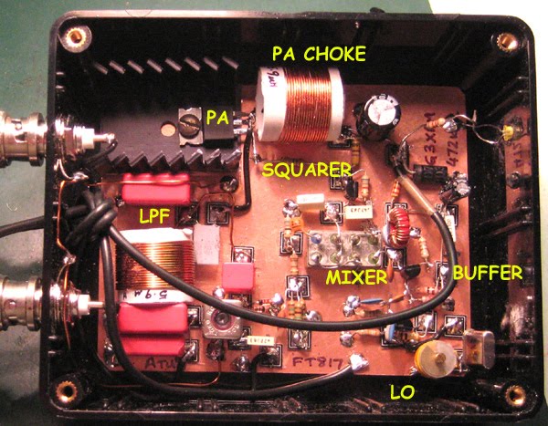
Although not available commercially, another popular 630m homebrew design is one from G3XBM which will also provide a way to get on the digital modes. He also has a 2200m design, should your interests be focused on that band.

G3XBM -630m Transverter
Any of these simple transverters are capable of controlling a higher-powered switching FET amplifier as your station progresses.

If you want something in the 'Collins category', the tranverters (both 2200m and 630m models) produced by VK4YB's Monitor Sensors provide around 70W output and are incredibly well designed and built. I have been very happily employing a 630m model for well over a year now ... my review of the transverter can be found here.

VK4YB - 630m Transverter
I suspect that we may soon see more commercial products become available over the next year but if you are handy with a soldering iron, building your transmitter will all be part of the 630m challenge!

I would like to put on a beacon. What do you suggest?

The best and most informational type of beacon is a WSPR mode beacon. A WSPR beacon operator can always determine where his beacon is being heard, in real time, along with how well it is being heard, by watching the uploaded 'spots' of his beacon on the WSPRnet. You will have much better coverage with this weak-signal mode beacon compared to one on CW ... for every CW report received, you would likely get ten times or more that number on WSPR.

Although WSPR is a great mode for checking out propagation, it's very easy to get into the habit of nightly beaconing and not developing your station any further. If you do run a WSPR beacon, be sure to try some of the other two-way modes such as CW or JT9 and call CQ regularly ... ham radio is all about making two-way contacts!

I don't have enough property for the large antennas required, so I won't be able to use these bands.

Even if you are limited in space, you can still enjoy these bands. There are many examples of stations on small city or suburban-size lots that are consistently heard across North America on 630m. If you have the room for an 80m or 40m dipole or inverted-L, that will be enough space to work these bands. An inverted-L for example, can be base-loaded and tuned to resonance. Along with several ground radials, even a small antenna system like this will allow you to work skywave DX or be heard across the country when propagation is good. I'm constantly amazed at how well these bands propagate with very low amounts of erp. Don't let living on a small lot stop you from exploring these bands!

All I hear is noise on these bands ... how can I use them if I can't hear anything?

Growing noise floors are common to everyone and this is often the biggest challenge for LF and MF operators, especially those in densely populated regions. Armed with a little knowledge and investigation, oftentimes seemingly impossible QRN can be substantially reduced if not eliminated entirely ... even easier when the noise source is found to be in your own home! While some amateurs just give up at this stage, most will see it as an interesting challenge to be overcome and part of the many learning experiences offered by these new bands.

In addition to the informational links provided above, I have just added a new 'Getting Started On 630m' page to my website. This page has a two-part article that I recently wrote for The Canadian Amateur, our national amateur radio journal. The articles describe a simple way of getting on 630m CW as well as providing some basic antenna information and ideas.

This blog also has extensive writings involving 630m over the past few years, describing equipment used and suggestions for new operators, much of it involving homebrewing. There are several links on the right that will take you to specific blogs dealing with 630m.

For present LF and MF operators here in Canada, the arrival of our American friends to these bands is generating much excitement and anticipation. The opening of these bands in the USA will pump new life into this part of the spectrum for all North American participants and the opportunities for homebrewing and experimenting are boundless. It should be a very exciting winter!

If you have not taken the 60 seconds required to register your station on the UTC webpage, please don't neglect to do this via the link provided above. There have, reportedly, been thousands of amateurs doing this already, as it effectively locks-out their locations for any future PLC deployment that might keep them off these bands at a later date.

See you in mid-October on 630!

Friday, 5 May 2017

LF / MF News From Monitor Sensors


A note from Roger, VK4YB of Monitor Sensors, reports some interesting news.


You might recall that his company manufactures a very versatile and well-engineered 630m transverter which was used at both ends of our two 630m JT9 contacts last year during the fall equinox propagation peak between North America and down-under.

Roger now reports that Monitor Sensors will be producing a new 2200m transverter, with all of the bells and whistles found on the 630m unit which has proven to be a real workhorse.


Monitor Sensors 2200m Transverter

The Monitor Sensors TVTR2 2200m Transverter enables any Amateur Radio Station, equipped with a conventional HF transceiver, immediate, all mode, access to the new 135.7-137.8 kHz, 2200m band.
The receiver design incorporates a 7pole Chebyshev filter, 3kHz wide roofing filter and a 5 pole Chebyshev filter in cascade before the double balanced, commutating mixer, fed by an ultra stable, temperature compensated, extremely low phase noise, MEMS local oscillator. The mixer is followed by a Chebychev band pass filter into an ultra linear, low noise, current feedback, IF amplifier. The receiver noise floor, in a 500Hz bandwidth, is -125 dBm and yet the onset of compression is not reached until +11dBm. A front end 20dB attenuator can be switched in for even higher signal handling. Overall receiver gain is set to +6dB, or -14dBm with attenuator in.


The transmitter input circuit incorporates a 0-14 dB switched step attenuator to prevent over driving. The same mixer and local oscillator are used on the transmit side. The PA uses 6 rugged lateral FETs in class AB push-pull to easily achieve the 50 watts rated output. Lateral FETs are inherently linear and thermally stable. The transmitter can be run at full power, indefinitely, into a dead short or open circuit without any danger of damaging the FETs. Transmit-receive switching is automatic with user selectable VOX delay. Alternatively the PTT line may be used.


The transverter employs extensive and accurate metering. Power input and output, SWR, Frequency, Attenuation in use, Temperature, Supply Voltage, Current and Resistance are displayed.
Transmission is inhibited if carrier frequencies outside the 135.7-137.8 kHz band are detected. A tuning screen may be selected which displays SWR in digital and graphical form for easy antenna adjustment. The menu system is self explanatory and users report no manual is needed, although one is supplied. A USB socket is provided for future code upgrades (free of charge) from the Monitor Sensors web site.


The transverter has been designed for the best possible protection against accidental mishaps. It will survive reverse polarity supply and the injection of 100 watts of HF into any of its ports whether in transmit or receive mode. If supply current exceeds 25 Amps, the supply is cut in 3 microseconds. This electronic breaker can be reset by simply switching off and on again. The transmitter will shut down in the unlikely event that the internal heat sink reaches 90°C. The cooling fan is under the proportional control of the microcomputer and begins operation above 35°C. Any unusual operation will cause the screen to turn red and an appropriate warning will be displayed.


TVTR2 Specifications


RF frequency range 135.7 to 137.8 kHz
IF frequency range 1805.7 to 1807.8 kHz (others available in the 160m band)
Transmission modes CW, SSB, WSPR, and all other data modes
Output Power 50 Watts Continuous, 100% duty cycle @13.8V supply
Input and Output Impedance 50 Ohms
Supply voltage 13.8 VDC @ 15 Amps nominal, 10-16 VDC operational
Rx noise floor -125 dBm (500 Hz bandwidth)
Rx 3dB compression point +15 dBm (Rx attenuator out)
Rx IF rejection better than 75dB
Rx conversion gain +6dB nominal
Roofing filter in-band ripple +/- 0.5dB
Tx 3rd order IMD -33 dB below PEP, typical at 50W output
Tx 5th order IMD -45dB below PEP, typical at 50W output
Tx harmonics and spurii All better than -50dB
Tx conversion gain +10dB nominal
Power input connector 2 * Anderson Power Poles (one Power cable supplied)
RF connectors 3 * SO239 (one PL259 to PL259 cable supplied)
PTT connectors 2 * RCA (one RCA to RCA cable supplied)
USB connector Micro B USB, (matching cable supplied)
Dimensions 12½ * 4¼ * 3 inches, 320 * 120 * 76 mm
Weight 3.4 lbs, 1.6 kg


In addition to the transverters, Monitor Sensors will also be manufacturing solid state amplifiers for both the 2200m and 630m bands with power levels at around the 450W output level. Like the transverters, these will be 'linear' devices as well. It is possible that a duo-band amplifier will also eventually be produced.

It will be interesting to see if any other new gear becomes commercially available from other manufacturers once the LF / MF ham bands are introduced in the U.S.A. , something that is expected to happen fairly soon.

Wednesday, 5 April 2017

The Artwork Of DK1IS


Recent discussion on the RSGB LF Group reflector about high-powered LF / MF amplifiers brought an interesting response from Tom, DK1IS, and his unique solution.

It's no secret that a Class D / E amplifier using switching MOSFETs is a popular and reasonably inexpensive method of generating some serious RF on the LF and MF bands. Equally well-known is their propensity to gobble-up FETs should the amplifiers encounter much reactance in their output load. Most builders include some form of protection for sudden over-current or unwanted SWR excursions which will shut down the amplifier before any FETs can self-destruct. Those that don't usually end up replacing FETs.


I would venture to guess that over 90% of the transmitters now being employed on LF or MF are using switching MOSFETs in a Class D / E design but there are some amateurs using vacuum tubes to do their heavy-lifting ... and with good results.

DK1IS's beautiful homebrew amplifier is shown below. Tom provided the following description:

Hi Wolf and group,

nice to hear that someone else is thinking about this approach! I´m
content with my homemade tube PA for LF and MF which has provided
reliable service since nearly 4 years now. Only some thoughts about this
concept - I hope not to bore all those hams who are happy with their
semiconductor PAs:

Years ago I had a MOSFET PA for LF, Class B push-pull with 250 W RF. It
worked well at constant conditions, but when I had to retune the antenna
due to larger QSY or made antenna experiments there always was the
danger of blowing up these nervous semiconductors. After 4 or 5 times
changing the MOSFETS I decided to build a new PA - with tubes! Looking a
little bit anachronistic this PA is absolutely good-natured. Designed for
broadband service on LF and MF it makes no problems when changing the
antenna coarse tuning from one band to the other even when the fine
tuning isn't done yet. With my former MOSFET-PA this would have been
impossible.

I wanted to have a linear PA - this usually means class B. You have to
decide between narrow band and broad band (like an audio-amp) design.
For narrow band you can use a single-ended PA but you have to add a
resonance circuit. For broad band you should use a push-pull PA and have
to build a suitable output transformer. I opted for broad band design
because it is usable for LF and MF without changes at the PA. With this
design and sin-driving I reach a total harmonic distortion of about 5 %
at 700 W RF on a pure resistive dummy load. With the usual narrow,
narrow band antennas on LF and MF you don´t need additional filters!

Concerning the tubes: If you take the common TX tubes with plate
voltages of several kV all output circuits have rather high impedances,
that means large coils for the resonance circuits resp. large
transformer windings and very high voltages - potentially a construction
problem. This led me to the choice of 2x 4x PL519 in push-pull, a rugged
colour TV line output tube with low plate voltage and high plate
current. In this way I came down to a plate-to-plate resistance of about
1 kOhm at 600 V DC plate voltage, where you easily can build a ferrite
broad band output transformer down to 50 Ohms. A disadvantage of this
concept is that you have to give individual bias to each tube, that
means for the first start-up you have to align 8 potentiometers
carefully to nearly equal cathode currents for all the tubes. But
according to my experience this alignment remains stable over a long
time. I have inserted 1-Ohm-resistors in each cathode line and have
brought the voltage drops to 8 cinch connectors, where I can monitor the
DC component (with external filtering) as well as the real time current.
With 4 tubes in parallel per branch of course you have to take care for
self oscillations. The extensive use of bypass capacitors, ferrite beads
and parasitic chokes in the plate lines is mandatory as well as good
grounding concepts are. The tubes don´t pull control grid current (this
would even be true in class C!) but you need 3 or 4 W RF input power due
to all the ohmic loads at the tube´s control grids caused by the
individual bias paths. On the other hand this certainly helps to avoid
oscillations. You can see some pictures of this PA at https://www.qrz.com/db/DK1IS

By the way: why not to try these tubes at class D? With DC plate
voltages of perhaps 1200 V you should get a nice QRO-PA ...

Wolf, you are right: building such a PA from scratch is a time consuming
enterprise. I didn´t count the working hours but according to my lab log
the whole project took about 9 months - an adequate time for a new baby!
It was a great experience anyway.

Good luck and 73,
Tom, DK1IS

2x 4x PL519 Push-Pull  


TX, power supply, RX, exciter
As 'day one' for U.S. amateurs gaining their new LF / MF bands draws closer, many are seriously thinking about building or modifying rigs to get on the air. I'm sure the use of switching MOSFET amplifiers will still reign supreme when it comes to decision-making time but with some feeling more comfortable with tube technology, especially when used for power amplifiers, I suspect we will see some interesting tube transmitters being employed as well. I'm sure that some will even seek to modify older tube rigs, knowing that a pair of 6146's can muster enough power to have plenty of fun on the new band as well.

DK1IS has provided an inspiring example of what can be done using vacuum tubes ... they certainly should not be discounted as a viable method of generating your hard-earned LF / MF ERP.

Thursday, 30 March 2017

LF and MF Now Very Close For U.S. Amateurs!


For U.S. amateurs anxiously awaiting implementation of the new 630m and 2200m bands, the wait seems to be almost over!


Good news came down late yesterday in the form of the FCC's "Report and Order" (ET Docket No. 15-99) which lays out the proposed rules and regulations that, barring any further changes, will likely become standard operating procedures once these two bands become finalized.

Highlights of the FCC's document are as follows:

1. Recognition that both Utilities (UTC) and amateurs can co-exist within these parts of the spectrum:

... co existence between PLC systems and amateur radio operations in these bands is possible, and the service rules we adopt in this Order will foster this co existence.

2. Amateurs operating within these bands must be no closer than 1 km from transmission lines that are actively carrying PLC (control) signals:

As proposed, we will permit amateur stations to operate in the 135.7-137.8 kHz and 472-479 kHz bands when separated by a specified distance from electric power transmission lines with PLC systems that use the same bands.   To support the operations of both the amateur service and PLC systems in these bands, we adopt a minimum horizontal separation distance of one kilometer between the transmission line and the amateur station when operating in these bands.

We find that a one kilometer separation distance reasonably ensures that PLC systems and amateur radio stations are unlikely to experience interference.  In addition, establishing a zone where amateur use is not authorized will simplify and streamline the process for determining whether an amateur station can transmit in these bands when in proximity to transmission lines upon which PLC systems operate.

3. Amateurs must "make notification" to local UTC authorities before commencing operation on either of these two bands:

We will require amateur operators to notify UTC of the location of their proposed station prior to commencing operations, to confirm that the station is not located within the one kilometer separation distance. 

The notification requirement will entail notifying UTC of the operator’s call sign and coordinates of the proposed station’s location for confirmation that the location is outside the one kilometer separation distance, or the relevant PLC system is not transmitting on the requested bands.  UTC, which maintains a database of PLC systems must respond to the notification within 30 days if it objects.  If UTC raises no objection, amateur radio operators may commence operations on the band identified in their notification.  The Wireless Telecommunications Bureau will issue a public notice providing the details for filing notifications with UTC.

A simple notification to UTC with a 30-day waiting period does not appear to be burdensome.  Amateur operations can commence as soon as that period expires.  ARRL claims that UTC should provide access to the PLC database to them or directly to amateurs to assist them in determining whether their notified operations are within the one-kilometer separation distance from transmission lines with PLC systems operating on these bands.  ARRL fails to make a persuasive case why it would be a better organization to make those determinations rather than UTC.  Further, since UTC has control of the PLC database which can be updated, we find no reason to mandate its release to another party especially considering the sensitive nature of information it contains.

4. Power limits will be expressed in EIRP as well as maximum PEP:

Amateur stations may operate in the 135.7-137.8 kHz band with a maximum radiated power of one watt EIRP ... that amateur stations operating in the 135.7-137.8 kHz band should be subject only to the general Part 97 limit of 1.5 kW peak envelope power (PEP).

We also adopt the power limits proposed in the WRC-12 NPRM for amateur stations operating in the 472-479 kHz band.   For such stations, the maximum radiated power will be five watts EIRP, except for stations located in the portion of Alaska that is within 800 kilometers of the Russian Federation, where the EIRP will be limited to one watt.  We also limit the transmitter power for amateur radio operations in the 472 479 kHz band to 500 watts PEP; provided, however, that the resulting radiated power does not exceed five watts EIRP.   In other words, it may be necessary to reduce transmitter power below 500 watts PEP to avoid exceeding the five watts EIRP limit.

5. Antenna height will be limited:

... we will require that the antennas used to transmit in these bands not exceed 60 meters in height above ground level (AGL), as ARRL proposed.

6. Regarding transmission modes, no bandwidths have been specified in order to encourage experimentation:

Consistent with our proposal in the WRC-12 NPRM,  and with the existing rules in Section 97.305 for the frequency bands below 30 MHz, we authorize amateur stations to transmit the following emission types throughout the new amateur bands: CW (international Morse code telegraphy), RTTY (narrow-band direct-printing telegraphy), data, phone, and image emissions.   These emission types provide amateur operators with maximum flexibility, and we find that additional restrictions would needlessly hinder experimentation.

7. Experimental stations appear to 'still be in business' but are encouraged to transition to the 'amateur' service:

Finally, we decline to permit previously licensed experimental stations – some of which have been authorized with significantly more radiated power than the adopted EIRP limits for these new amateur service bands – to communicate with amateur stations operating in these bands.  Amateur operations in these bands currently authorized under experimental licenses should transition their operations in accordance with the adopted rules and not circumvent such rules by use of experimental licenses.

My understanding of the R&O document is that participating parties may still file a 'Petition For Reconsideration' notification within 30 days of the R&O's publication in the Federal Register. Once these (if any) are dealt with, there are no other roadblocks preventing immediate implementation.

The document contains additional details not discussed here and makes fascinating reading for amateurs that might be looking forward to the new allocations.

This is the news that many U.S. amateurs have been waiting many years to hear! It is also good news for Canadian's operating on these bands to know that they may soon see a large increase in activity south of the border. Let's hope things continue to transpire favorably and that we will finally see the new bands become a reality.

Get those soldering irons out guys and gals!

Monday, 26 September 2016

The Amazing BOG

courtesy: http://www.wd0m.com/antennas1.html

A recent inquiry about 'BOG' antennas on the topband reflector reminded me of my own experiences with this simple yet very effective antenna. A 'BOG' or 'Beverage On Ground' seems to come in many varieties and is usually, out of necessity, shorter than a 'real' beverage.

In many instances, BOGs are as simple as running a wire out on the ground as long and as straight as practical. Not always, but usually, the BOG is fed by a small homemade balun to isolate and match the impedance to a 50 ohm feedline. Most real Beverages are terminated at the far end with a resistor to ground, while for BOG builders, some use it and some don't.

My own experience with a BOG, or as close as I could come to one, was an extension of my 160m half-sloper. The topband half-sloper was quite normal, being about 132' long and fed at the top of its supporting metal tower with 50 ohm coax ... the hot-side of the coax going to the wire and the shield going to the metal tower.

One afternoon I wondered how the antenna would work lower in frequency, in the NDB band below the broadcast band, if I were to extend the sloping 132' element further. I added another length of wire to the lower end and proceeded to run the wire along the ground on the bankside above the beach. I was able to run out another 500' approximately, in a straight line to the east, before running out of beach. I left the far end unterminated and waited for darkness to to have a listen.

The first thing I noticed when tuning the NDB band was how quiet it sounded. There seemed to be almost no noise, man-made or nature-made. Disconnecting the antenna showed a small drop in what little noise there was, indicating that sensitivity levels were still being determined by skynoise ... a good thing.

What amazed me however, was that signals just popped-up everywhere and although not as strong as on my normal NDB antenna (a loop at the time), they were much better copy since there was virtually no noise. The BOG produced a significant improvement in my SNR on all signals. It had been several months since I had logged any new beacons on the NDB band but over the next three weeks I was able to put 65 new catches in the log ... all previously unheard!  Switching between the loop and the BOG almost always produced no copy at all on the new signals, compared to an easily copied one on the BOG.

My experience was very similar to that shown in these videos by VO1HP ... with solid signals well out of the low noise background and no sign of atmospheric noise to mask them.


It is clearly evident that the BOG delivers a much better SNR than the comparison loop and is the reason so many topbanders use a separate antenna for receiving. The next video compares the BOG with a 160m 'Inverted-L', a very popular antenna on topband.


BOGs need not be really long and good results can be had with just 200' of wire. Many BOG users employ a simple preamp to boost the low level of signal but often the switchable 'preamp' built into a receiver or transceiver will be enough to overcome the low gain of shorter wires.

I've often thought that if I had a lot of acreage, the ideal receiving system for MF and LF work would be a centrally located radio shack with long Beverage wires fed-out in various directions ... like the spokes of a wheel. Having the ability to directionally switch antennas would produce 'beam-like' capabilities on LF.

There is a ton of web information available on the BOG and the Beverage should you want to give this simple antenna a try and have a narrow strip of space where one might be laid out without causing a problem.

A very comprehensive source of BOG and Beverage information can be found on WØBTU's Beverage Receiving Antennas page here. 

A nice compilation of Beverage / BOG exchanges from the Topband Reflector may be found on N1EU's Beverage Antenna Tips page here.
 
In addition, N1EU has a useful page of discussion about transformers used in these antennas.

PA5MW offers a colorful description of his own BOG experience here.

Bruce, K1FZ has a nice BOG 'hint's' page here and also passed this advise to the original BOG inquiry:

A BOG can do a good job unterminated. If too long they self terminate. Depends upon the soil as to length.

The biggest mistake is making the BOG antenna too long. Try not to go
over 200 feet for 160 meters. Longer will work in some locations
soil like desert, sand, other non/ partial conducting types.

Its been a few years since my last experience with a BOG but I may run one out again for the DX season, now that most of my neighbours have left the island for the winter.

Tuesday, 12 July 2016

Nightly 75kHz WSPR Activity From Arizona - WH2XND


2.5mH 136kHz loading coil at WH2XND

For the past few weeks, Ron, NI7J in Phoenix, has been activating his experimental station, WH2XND, in the LF band ... on 75.550kHz (WSPR), where he is licenced to operate.

Last night I decided to put my nightly 630m WSPR beacon on hold and have a listen for Ron's signal using my 10' x 20' loop.


Ron's main experimental operating has been on 630m and 2200m WSPR mode but his recent activity on 75kHz has sparked a lot of interest among dedicated summertime listeners. WH2XND is licenced for 10W ERP on 75kHz, not a number that's easy to muster considering the poor antenna efficiency produced by typical amateur installations ... however, judging from Ron's coils, his installation looks far from 'typical'!

Ron's signal is being well heard, even up in Alaska, in spite of the noisy summer conditions and it will be interesting to see how well it propagates once we move into the fall and quieter winter nights.

The big loop seemed to do well with Ron's signal last night, resulting in 55 decodes starting at around 2300 local time and continuing to sunrise.

Timestamp                    Call                   SNR         Grid  
  
2016-07-12 12:28      WH2XND            -28            DM33xt     
2016-07-12 12:20      WH2XND            -27            DM33xt     
2016-07-12 12:16      WH2XND            -25            DM33xt     
2016-07-12 12:12      WH2XND            -28            DM33xt     
2016-07-12 12:08      WH2XND            -27            DM33xt   
2016-07-12 12:04      WH2XND            -28            DM33xt     
2016-07-12 12:00      WH2XND            -29            DM33xt     
2016-07-12 11:40      WH2XND            -25            DM33xt     
2016-07-12 11:36      WH2XND            -20            DM33xt     
2016-07-12 11:32      WH2XND            -18            DM33xt     
2016-07-12 11:28      WH2XND            -18            DM33xt     
2016-07-12 11:24      WH2XND            -19            DM33xt     
2016-07-12 11:20      WH2XND            -19            DM33xt     
2016-07-12 11:16      WH2XND            -20            DM33xt
2016-07-12 11:12      WH2XND            -20            DM33xt     
2016-07-12 11:08      WH2XND            -19            DM33xt      
2016-07-12 11:04      WH2XND            -19            DM33xt      
2016-07-12 11:00      WH2XND            -20            DM33xt     
2016-07-12 10:56      WH2XND            -20            DM33xt   
  
2016-07-12 10:52      WH2XND            -21            DM33xt      
2016-07-12 10:48      WH2XND            -22            DM33xt      
2016-07-12 10:44      WH2XND            -23            DM33xt      
2016-07-12 10:40      WH2XND            -24            DM33xt      
2016-07-12 10:36      WH2XND            -25            DM33xt      
2016-07-12 10:32      WH2XND            -26            DM33xt      
2016-07-12 10:28      WH2XND            -24            DM33xt      
2016-07-12 10:24      WH2XND            -24            DM33xt      
2016-07-12 10:20      WH2XND            -25            DM33xt     
2016-07-12 10:16      WH2XND            -24            DM33xt     
2016-07-12 10:12      WH2XND            -23            DM33xt      
2016-07-12 10:08      WH2XND            -26            DM33xt      
2016-07-12 10:04      WH2XND            -25            DM33xt      
2016-07-12 10:00      WH2XND            -26            DM33xt      
2016-07-12 09:56      WH2XND            -26            DM33xt      
2016-07-12 09:52      WH2XND            -27            DM33xt      
2016-07-12 09:40      WH2XND            -26            DM33xt      
2016-07-12 09:36      WH2XND            -25            DM33xt     
2016-07-12 09:32      WH2XND            -24            DM33xt      
2016-07-12 09:28      WH2XND            -26            DM33xt      
2016-07-12 09:24      WH2XND            -26            DM33xt      
2016-07-12 09:20      WH2XND            -28            DM33xt      
2016-07-12 09:16      WH2XND            -27            DM33xt      
2016-07-12 09:08      WH2XND            -27            DM33xt      
2016-07-12 09:00      WH2XND            -27            DM33xt      
2016-07-12 08:56      WH2XND            -28            DM33xt      
2016-07-12 08:52      WH2XND            -29            DM33xt      
2016-07-12 08:44      WH2XND            -29            DM33xt      
2016-07-12 08:40      WH2XND            -27            DM33xt      
2016-07-12 08:36      WH2XND            -28            DM33xt      
2016-07-12 06:44      WH2XND            -32            DM33xt      
2016-07-12 06:32      WH2XND            -31            DM33xt      
2016-07-12 06:28      WH2XND            -31            DM33xt      
2016-07-12 06:24      WH2XND            -30            DM33xt      
2016-07-12 06:20      WH2XND            -30            DM33xt     
2016-07-12 06:12      WH2XND            -29            DM33xt  
    

His signal peaked here (shown in blue above) about an hour before sunrise, with almost a dozen decodes in the -18 to -20 region ... not far from audible CW levels which will probably be seen in winter. It was interesting to note as well, that in several transmitting sequences, Ron's signal was stronger in Alaska than it was here and in Washington state ... just the opposite of what one might expect.

In the past, I have had good results on 75kHz with Dex (W4DEX), when listening for his QRSS CW signal, using my normal inverted -L with a 2.5mH RFC inserted in series with the antenna's normal loading coil.


'XRS/5' on 75kHz from W4DEX in NC
If you can give a listen for Ron's WSPR signal and send him a report ... or better yet, upload your spots to the WSPRnet site, he would be very appreciative. For listening, set your receive frequency to .074kHz in the USB mode. The software will take care of the rest. You can upload 'LF' spots with your software by setting the '.074' receive frequency in the program's normal frequency or band window.

Friday, 8 July 2016

Is Your Miniwhip Too High?

The Mini-Whip at University of Twente's (Netherlands) Remote Receiver

A recent posting to the 'ndblist group' described an interesting experiment by Dirk Claessens regarding the signal-to-noise ratio (SNR) versus height of his PAØRDT active whip. Dirk's tests were posted on the 'Navtex DXing Group' where some further interesting discussion seemed to confirm his findings.

Here is what Dirk discovered, backed-up with his graph data, clearly pointing to the 'ideal height' at his location ... and probably yours as well.

Hi all,

You may recall that to get rid of a source of QRM, my whip is now hanging from a rope-and-pulley system, about 5 .5 mtr from the house, at a height of 7 meter agl.
As the height of the whip can easily be changed, this is an ideal situation to test the behaviour of the whip wrt noise levels, optimal height etc..
I had done this test before some 4 years ago, but not very precise. Time to do it again, and documenting it.
What I also wanted to check, is if there were any noise sources of the own house possibly reaching the whip.
(how far does the "noise bubble" go in function of the height?)

The Perseus was tuned to 549 KHz Deutschlandfunk Nordkirchen, the station closest to 518.
2 markers were set, one to the signal, and a reference marker in a quiet spot nearby on 543 KHz, to get a reading for the noise floor.
The whip was then lowered in "1 meter each minute" steps, readings were taken and written to the marker file.

First the absolute values were plotted.
Note that: blue = noise floor, red = signal, and that the left and right axis scales have identical spans of 19dB, but are shifted, in order to get a compact graph.
We see that for a delta height of 6 meters:
-the noise floor goes up ~8dB, or 8/6 = 1.3 dB/m, almost linearly.
-the signal goes up ~14 dB, or 14/6 = 2.3 dB/m, clearly curved and showing a maximum at ~5..7 m.
The continuous lines are polynomic (2nd degree) regression lines.


The noise on the measurement values seems to increase with decreasing height.  Was this caused by my body standing under the whip, and near to the whip for the lowest measurements??

What really matters of course, is the signal over noise value, this is plotted below:


-Within a narrow 1 dB band, the curve shows a clear optimum in the region of 4..7 m agl, a familiar value often given as optimal by Roelof.
-The measurement was performed during the day and thus with ground wave propagation. As the whip is truly omnidirectional, I cannot see a reason why the behaviour would be different at low angle DX signals.
- At 5.5 meter from the house, the whip seems to be outside of the "noise bubble"

and later, following discussion:

I have just checked the noise floor again at 518 (with no signal present)

Perseus set to 125 kS/s, Span/RBW 25/30.5
Shield grounded: -125 dBm
Not grounded:  -110 dBm

That's a whopping 15 dB difference!
I have also buried the coax ~20cm deep from the grounding point to where it enters the house.

The ideal height was also that recommended by Roelof, PAØRDT, originally and points out that one of antenna-building's most sacred commandments ... "the higher the better", is not always true!

I have often recommended this simple antenna for those looking for a very effective yet low-footprint receiving antenna for use on the LF and MF bands.

Much more information about Roelof's popular miniwhip may be found in previous blog discussions here.