Showing posts with label crystal radio. Show all posts

Sunday, 22 December 2024

Finding Your Best Crystal Radio 'DX Diode' (Part 2)


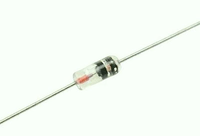
Readers may recall my summertime blog, "Finding Your Best Crystal Radio ‘DX Diode'". It described a theoretical method I tried in order to see which of several dozen diodes might emerge as the best of the show, or in crystal radio DX circles, the ‘Holy Grail Diode’!

The grading system revolved around the combination of several factors … the diode’s measured forward-voltage (Vf), the weakest signal level detectable from an RF oscillator (whose level could be varied) and the diode's current when detecting a fixed-level signal on 1220 kHz. These values were used to derive a numerical ranking that I called ‘Vdx’, which would hopefully rank the best overall performers!

It’s not unreasonable to think that diodes with a very low forward voltage (Vf) combined with the ability to detect the weakest signal from the signal generator, might likely be the best diodes in the bunch … or are they?

These tests capacitively-coupled the oscillator signal directly into the crystal radio’s antenna tuner, which then coupled them into the detector stage. Using the methodology described in the earlier blog, the 48 diodes under review were narrowed to the ‘top 10’ likeliest best performers.

This time, actual ‘on-the-air’ signals would be used to compare diodes against each other in real time. A closer look at the top candidate diodes was made over several days and evenings as the days grew shorter and darkness arrived earlier.

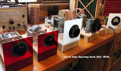
My DX set has provisions for comparing a current good performing diode against two others.


In this arrangement, shown above, the current ‘best diode’ is mounted in the center switch position so that an immediate comparison can be made between it and the other two in real time.

A weak groundwave signal from Seattle, with a slow fade rate, was used initially but nighttime skywave signals were found to be most useful. Several  hours were spent tuned to 2800 watt CKBI in Prince Albert, Saskatchewan on 900 kHz. Their C&W format meant that most of the time they were broadcasting music, which I've found is always much easier for the ear-brain to detect in the noise floor than are spoken voices.

So what did I eventually find out? My original ranking methodology concluded that the best overall diode of the many dozens was the Sylvania JHS 1N3655A, a 40-year old microwave mixer diode.


The observations of the CKBI signal strength were by ear-brain only and no actual levels were measured since signal levels were usually too weak to measure on my detector's micro-ammeter. Measurements may yet be undertaken using an oscilloscope or by using an audio amplified output to compare signal voltage levels.

So … would my diode-ranking order and testing methodology hold up when actually using the diodes in a hi-end, low-loss crystal radio system when connected to an actual antenna?

I started ‘A-B’ comparisons against what has always been a reliably good performer mounted in the center position, a fairly modern twenty-year old  1N34A.

As noted above, the #1 rated diode (with my Vdx rating of 66) was the 1N3655A microwave mixer diode. Although it did not produce the loudest signal (diode current) compared with others, it had an exceptionally low Vf of .18V and its weak-signal detection level was good although not the lowest. Like a few others, it detected the nearby UHF data stream ‘clicks’ from a nearby Wi-Fi modem, often a characteristic of a good performer.

I was somewhat aghast when my #1 ranked 1N3655A was immediately outperformed by the modern 1N34A, ranked 44 out of 49! The 1N3655A was not just poorer than the 1N34A, it was very poor by comparison ... hmm ...was my selection process really that far off?

Diode #2, also with a low Vf of .197V was also poorer than the 1N34A, whose Vf was an unimpressive .375V.

And so it went for the most part, with my top 10 choices! Most of them were equal to the 1N34A but nothing stood out while listening to real on-air signals until I got to the three ‘curiosity’ diodes, originally tested at the very end.

The 38th-ranked Soviet-era D18, a military grade germanium in a glass ‘50s-style' package, was compared next. Earlier testing had shown it to produce a loud signal (higher current) but combined with its high Vf of .366V led to a low overall ranking.

Surprisingly, the D18 produced a noticeably better signal than the 1N34A and was moved into the #1 position.


Next up was the FO-215, often touted as the Holy Grail diode. It compared favorably with the D18 but was no better. Some have found that paralleling two FO-215s produced even better results but I did not find that to be the case.
                                                                                

The third diode was a very old Sylvania 1N34A from the 50s, possibly one of the earliest in production. It had an unimpressive Vf of .335V but did produce a loud signal in earlier testing. It detected the signal from Saskatchewan equal to or perhaps slightly better than the D18 … it was hard to say for sure. It was certainly no worse!


These last two were both made in the 50s … was there something different about the way they were made? Was the germanium different back then? How did they perform so well when their Vf was so high? It almost appears the opposite of what might be expected.

Seeing the above behaviour, I couldn’t pass up the chance of testing the 48th ranking diode, a beautiful black NOS Rogers 1N34A, probably another product of the 50s. Its Vf was truly discouraging, at .401V and the reason I had mostly ignored it in the past. It was put up against the D18.


I was astounded to find that not only was the vintage black beauty better than the D18, it was a LOT better! The ‘just barely’ detectable CKBI signal popped out of the noise to become one that was easy to hear! I had to rock the ‘A-B’ switch back and forth many times just to enjoy the big difference!

Out of curiosity, I tested the last-ranking diode (Vf of .444V) and it truly was deaf, with not even a sound emitting from the phones … so at least I got that one right!

What is obvious now is that the method I used to rank the diodes was flawed. These results have brought up several questions for me that I had never considered previously … far more questions than answers!

Takeaways? I've found that there's a lot about diodes that I don't know and need to learn about! I’ve learned that a diode’s Vf value is not an indicator of its weak-signal detection capability in crystal detectors (in spite of what some You Tube videos might try to convey). I've learned that when detecting a weak signal, the diode is operating below its Vf value which helps explain why a high Vf value does not mean a poor detector or a low Vf does not mean a good detector. Low Vf values were a well considered number when ranking my diodes … an apparent mistake.

Further to this, the diode is operating within its ‘square law region’ when detecting the weak signals we seek. When operating in this region, it means that increasing the input signal by 5 times (for example) will increase its output by 25 times. Similarly, decreasing the input level by 5 times will result in a 25 times drop in output. The importance of reducing as many losses as possible in the antenna tuning stage along with the detector stage itself can certainly pay fast dividends when it comes to weak signal detection. Conversely, ignoring system losses will very quickly reduce performance.

Also ignored in my system was diode capacitance, diode operating impedance, reverse leakage and no doubt some characteristics I'm not even aware of. Diodes with lower C will have fewer losses than those that are higher. I wonder how much of a factor was this in my overall unexpected results! The diode’s internal resistance when detecting a signal is a factor that I did not consider. The method of determining this value is complex but it may explain some of what I noticed.

There appears to be something different with older diodes that makes them great performers … larger junction? Germanium quality?

A final take away ... with enough knowledge, one can measure every tiny detail about a given diode without actually using it. No doubt a ranking list of diodes going through such rigorous scrutiny could zero-in on the top few. What's the BEST diode to use? It's probably the one that seems to work the best in your particular detector, until a better one comes along ... but it appears you can't go too far wrong with a very good 1N34A ... even in 2024!


Saturday, 20 July 2024

Finding Your Best Crystal Radio 'DX Diode' (Part 1)


Over the past few weeks I’ve had time to examine many dozens of diodes, mostly germanium, in my crystal radio diode collection. Many of them were removed from equipment built in the '50s and '60s (old diode matrix boards), some are vintage NIB 1N34As while others are modern SMD Schottky style diodes.

 
There are numerous excellent websites such as this one by Dick Kleijer or  SV3ORA's site  ... all describing elaborate ways to determine which diode is ‘the best one’ (the holy grail diode!) for crystal radio work. Most methods use a vigorous, somewhat complex test procedure plus a lot of math, most of which is well beyond my old brain, in attempts to flesh out each diode’s inherent characteristics ... as the sites referenced above illustrate, the simple appearance of a crystal diode belies its complexity and determining  diode behaviours can be more challenging than one might suspect.

My testing procedures were much more basic, and in the end, may hopefully reveal the best diode in my collection. I think one needs to undertake this with the understanding that there really is no overall ‘best' crystal radio diode but rather, only a diode that is best for your particular system and what works best in my system may not necessarily be the best one in yours.
 
My plan was to measure a few diode behaviors, shrink the list of candidates and then compare them against each other in my system's high-Q tank circuit.


My first step was to measure Vf or the forward voltage needed to ‘turn the diode on’. This can usually be determined to reasonable accuracy by using the diode test function on most digital multimeters. I’ve always supposed that the diode with the lowest Vf  turn-on threshold would probably be the most sensitive, but is it the only factor? Hopefully my tests would indicate if anything else is in play.
 
The next task was to determine the minimum signal level of a 1000 Hz modulated carrier on 1400 kHz that could be detected by each candidate diode. An RF probe was used to measure the level of signal capacitively coupled into my crystal radio’s antenna tuning stage which was then lightly coupled  into the detector stage, using the diode under test. No importance was given to the actual base level of this signal other than to note the level at which it could first be detected by ear (using sound powered phones) and making sure the coupling distance between stages remained the same for all diodes under test. This allowed me to compare weak-signal diode ‘sensitivity’ to the diode’s previously measured turn-on point or Vf value. Would the diode with the lowest Vf also be the most sensitive when used in a detector circuit composed of complex impedance, resistance, reactance and capacitance values that the test diode would be looking into?
 
The RF signal coupling was adjusted so the injected carrier could be varied between 0 and 10mV as measured on the RF probe. For each diode, the signal level was slowly increased from ‘0’ until the 1400kHz tone-modulated AM signal could first be detected.
 
The lowest 'first detected' signal level was .6mV while the highest level required 3.4mV, representing a pretty good range of diode behaviours. There were 49 different diodes in the test pool.
 
Four of the 49 diodes detected the .6mV signal, six detected the signal at .7mV, and nine first detected the signal at .8mV. The remainder required a still higher level of injected signal. The average level of first detection was 1.2 mV.
 
Of the four .6mV ‘best detectors’, their turn-on Vf values ranged from .15V to .38V while the .7mV and .8mV detectors had a Vf between .181V and .40V!
 
It seemed, not surprisingly, that generally the higher the Vf turn-on threshold, the greater was the level of signal injection needed for first detection … but evidently using the Vf value alone to determine the ‘best diode’ was not the hard axiom I had always assumed it to be!
 
Since a low Vf was not necessarily needed for good sensitivity, would there by any other tests that might indicate best performance?
 
The next trial was to measure actual diode currents in my hi-Q detector while receiving a lightly-coupled constant level input signal (1400kHz) to see how this value related to Vf. Measured diode currents (Id) varied from 9uA to 14uA for the same level of input signal, with the diode having the lowest Vf also producing the lowest current level ... hhhm! There was more to this than I expected, but generally, the lower valued Vf diodes tended to produce the most current and consequently the louder headphone signal … but not always! Some diodes with a Vf as high as .46V yielded high currents!
 
This now begged the question, “Does the higher current diode with a higher turn on (Vf) prove to be a better overall performer than the diode that turns-on early but produces a weaker signal?” What is the relationship between diode current and weak signal detection?
 
The next step was to express the relationship mathematically by calculating the ratio between the diode’s Vf and the level of diode current  (Id) measured in the previous test (Id / Vf). Each diode could then be assigned a number (Vdx) that might possibly indicate it’s true performance potential in my own system.

The diodes with the highest Vdx values would then be A-B tested under real receive conditions to see if any (or just one!) particular winner(s) might emerge … and if Vf was as critical as initially believed.
 

The Vdx values proved most interesting and seemed to account for some of the anomalies noted in earlier measurements with some of the higher Vdx values coming from diodes not necessarily with a low Vf. I’m hoping that this sorting concept properly takes into account both turn-on level (Vf) and current level (Id), since a higher level in either number will compensate for a lower level in the other. Vdx values ranged from 23 to 66, with seven diodes in the higher 53-66 range.


Click Image For Larger View


All of the 49 diode's test parameters were put onto a spreadsheet and listed in order of their Vdx value.


Click Image For Diode Spreadsheet Data


The highest Vdx assignment of 66 went to my 40-year junkbox resident, a JHS Sylvania 1N3655A microwave mixer diode. It will be interesting to see if it really is the best of the lot! Although it did not produce the loudest signal (Id) compared with others, its Vf turn-on was an impressive .181V and its weak-signal detection level was good although not the lowest. A couple of the UHF diodes exhibited the interesting behaviour of picking up the UHF data stream 'clicks' from my nearby wifi booster. The 1N3655A was one of them.
 
1N3655A Vf = .181V Id = 12uA Vdx = 66
   

Diode #2, with a Vdx of 62, is a mystery diode with a very low Vf of .197V. It was slightly louder and oddly enough, dug down slightly further than the 1N3655A, which had a slightly lower Vf. Although I don’t recall specifically, I suspect the diode may have been removed from a VCR front end many years ago.
 

Mystery diode  Vf =.197V  Id = 12.2uA Vdx = 62
 

Diode #3 with a Vdx of 61 is a modern SMS7630 Schottky microwave detector diode in an SMD package. Although it did not produce a competitive level of loudness (Id) in the diode current test, its shockingly low Vf turn-on of .147V and weak-signal detection threshold were the best of all diodes tested. Before testing, all SMD diodes were mounted on small PC boards in order to attach leads.
 

SMS7630 Schottky  Vf = .147V  Id = 9uA Vdx = 61


Diode #4 (Vdx of 60) is an ISS98, another modern Schottky microwave detector. I recall seeing this diode recommended for good performance in an FM crystal radio detector. Its sensitivity level was excellent.
 

ISS98 Schottky Vf = .211V  Id = 12.5uA Vdx = 60


Diode #5 (also with a Vdx of 60) appears to be a normal germanium of unknown type. I suspect it was used as an RF mixer since it was found on a small printed circuit board with three others, connected in a diode ring configuration typically seen in balanced RF mixers. It produced high current as well as good weak signal capability. 
 

Mystery diode Vf = .22  Id = 13.2uA Vdx = 60


Diode #6 (Vdx of 55) also looks like a germanium of unknown type with a body striping of gray-white-green-gray. If the last band is ignored, this could be a 1N895, a UHF germanium diode. It shows the typical internal cat-whisker type of junction often seen on the 1N34 germaniums.
 

Mystery diode Vf = .238V  Id = 13uA Vdx = 55


Diode #7 with a Vdx of 53 is marked as a ‘95481’ on a green body. It had excellent sensitivity and produced a strong signal (Id), elevating it to the top tier to be looked at more closely.


'95481'  Vf = .246V  Id = 13uA Vdx = 53


Diode #8, another germanium mystery, earned a Vdx of 49 due to its fairly high Id level.


Black 'T'. Vf = .258V  Id = 12.5uA  Vdx = 49


The rather beat-up looking Diode #9 is marked with what appear to be house numbers, '1846' and '6628'. I believe this was pulled from an old portable radio's FM section many years ago. Interestingly, like some of the UHF mixer diodes, '1846 / 6628' detects my high speed modem data stream clicks. Additionally, this tortured specimen produced the highest level of signal among all 49 diodes, with an Id of 14uA.


Vf = .294V  Vdx = 48 Vdx = 14 (Schottky?)


Diode #10 appears to be the brother of Diode #8 with a Vdx of 48. Although it has a lower turn-on point and was a better weak signal detector, it did not produce as much Id as its sibling, dropping it one notch lower on the list. Like its brother, it also has the mystery 'T' marking. Both are most likely unmarked 1N34As.

Vf = .252V  Id = 12 Vdx = 48


As well, three other diodes garnered my interest. Although they ranked lower than I expected, all had previously been found to be good detectors in my system. Their lower ranking may be a hint that my system of grading is not a valid method of determining best performance. All three will be given a harder look in the upcoming elimination tests.

The first is the germanium FO-215. Often touted as 'the holy grail' crystal radio diode but I have never found it to be particularly outstanding. Maybe my system has a lower Q than it really needs in order to show its stuff. This diode is shown on the bar graph above as #11. During testing, it appeared much less capable of weak signal detection than most others but its low Vf and high Id elevated its overall ranking.

Vf = .272V  Id = 13uA  Vdx = 48


The second diode is the Soviet-era D18, a military-grade germanium in a glass '50s-style package. I have previously found it to be a very good detector but its high turn-on level lowered its ranking. The D18 appears on the bar graph as #12.


Vf = .366V  Id = 12.2uA Vdx = 33


The third diode is a vintage Sylvania 1N34 from the 50s and likely one of the first 1N34s to be manufactured. Although it produces a loud signal, its Vf was higher than expected. As I recall, it was salvaged from an old parted-out Heathkit.  It appears on the bar graph as #13.


Vf = .335V  Id = 13uA  Vdx = 39


As mentioned earlier, one can measure and calculate a large amount of data for crystal diodes while they sit passively on the bench but they really need to be mounted, tested and compared in the actual system in which they will be used. Comparing diodes 'A-B' style in real time with weak signals may be better than any measurements made on a diode being bench-tested. 

Will a new ‘holy-grail’ emerge from the pile? This type of testing requires a lot of careful listening so time will tell. 

Testing will be ongoing over the summer / fall months ... stay tuned for the final results, hopefully in time for the fall DX season!

Saturday, 15 October 2022

Recent Crystal Radio DX Group 'Listening Event'


Crystal Shortwave Receiver of Al Klase (N3FRQ) 
 

The Facebook Crystal Radio DX Group’s fall listening event was held two weekends ago over a two-night listening period. Unlike last year’s event, this was not a contest but rather a leisurely opportunity for members to take some time to see what they could hear with their setups. Also unlike last year, this one introduced and encouraged members to see what they might hear on shortwave! Since circuits losses are measurably much higher as you climb above the broadcast band, audio amplification (AF) was permitted to encourage members to give it a try as this was a whole new region to explore for most of us.

The addition of shortwave inspired much discussion as well as construction, the main objectives of founding the group.

Shortwave crystal radio was all new to me as well and I struggled for several days, right up to the event’s starting time, to even be able to detect a signal. I had chosen to follow a similar path as described in WU2D’s excellent video, using simple link coupling into the detector tank circuit. I reasoned (probably incorrectly) that my end-fed 80m halfwave inverted-V would be close enough to resonating on the 5, 6 and 7 MHz SW bands to provide enough signal into the detector. After playing with this system as well as other antennas for several days, I eventually abandoned the concept and tried a different approach.

I added a loosely coupled tuned antenna input using my 630m inverted-V wire, bypassing its large loading coil and low-impedance matching system. Essentially it was a big vertical long wire tuned against a number of buried ground radials. I also added an LM386 audio stage between the detector and headphones, something I had not tried with the previous system.
 
This simple approach immediately produced signals … just in time for the start of the party at sunset!


Obviously, from just the physical appearance of my own SW tuner, there is a vast amount of room for improvement! As crude as it was, the following signals were all heard and verified on a separate SW spotter radio.

Oct 1

0250 10000 WWV Colorado
0255 7365 Radio Marti, Greenville, NC - Spanish
0305 9850 Radio Romania Int'l, Tiganesti, Romania - English
0310 9790 China Radio Int'l (CRI) Quivican, Cuba - English
0315 7375 Radio Romania Int'l, Tiganesti, Romania - English
0320 7335 Radio Marti, Greenville, NC - Spanish
0355 5000 WWV Colorado
0400 5935 WWCR, Nashville, TN - English
0408 5085 WTWW, Lebanon, TN - English
0429 4840 WWCR, Nashville, TN - English
0435 6000 Radio Habana Cuba, Quivican, Cuba - English
1411 6075 China National Radio 1(CNR), Baoji-Sifangshan, PRC - Chinese
1416 5980 Radio New Zealand, Rangitaki, NZ - English
1420 5965 CRI, Xianyang, PRC - Korean
1424 6125 CNR1, Beijing, PRC - Chinese
1426 6175 Voice of China, Beijing - Chinese
1428 7200 National Unity Radio, Tamsui District, Taiwan - Korean
1434 7410 CRI, Jinhua, PRC - Japanese
1436 7395 CRI, Kashi-Saibagh, PRC - Chinese
1437 7365 Voice of China, Shijiazhuang, PRC - Chinese
1452 9410 Voice of America, Tinang, Philippines - Korean
1741 12095 BBC, Kranji, Singapore - Korean
1745 11870 CRI, Urumqi Hutubi, PRC - Russian
2045 15000 WWV, Colorado
2312 11780 Radio Nat'l Amazonia, Brasilia, Brazil - Portuguese
Oct 2
1212 7245 Radio New Zealand, Rangitaki, NZ - English
1214 7310 CNR1, unknown tx site - Chinese
1220 7325 CRI, Jinhua, PRC - Japanese
1230 7355 KNLS, Anchor Point, AK - English
1240 7490 WWCR, Nashville, TN - English
1300 9675 CRI, Shijiazhuang, PRC - Russian
1307 9350 Voice of America, Tinang, Philippines - Korean
1311 9435 Voice of Korea, Kujang, N. Korea - English
1350 9265 WINB, Red Lion, PA - English
1740 9580 KNLS, Anchor Point, AK - Russian
1800 15580 VOA, Selebi-Phikwe, Botsawna - English

Reviewing many of the vintage radio magazines from the late 20s and early 30s, there appears to be very little published material from this era. I found this somewhat surprising but then perhaps not ... maybe most radio-buffs were still entranced by the new regenerative circuits popping-up every month and had little appetite for crystal SW receivers.
 
It would appear that even today there has not been much investigation or experimentation in building an efficient low-loss crystal receiving system for shortwave … somewhat of a golden opportunity for today’s crop of crystal radio builders!

In view of the above, along with a surprising amount of interest in SW during our recent listening event, I’d like to include SW in all future events going forward and possibly encourage even more new interest in developing efficient circuits. Is it practical to consider non-audio amplification for such circuit’s? Time will tell but already, several members are having measured success with just bare headphones!

Some of the BCB and SW construction inspired by the recent listening event is shown below. For more information and more sets, please visit the Facebook Group and consider taking part in our next event, sometime in December ... maybe you can build the perfect SW tuner!


Terry Jean Double-Tuned Loopstick BCB Tuner


James Kern Double-Tuned BCB Tuner


Ferhat Yavas Shortwave Tuner


Armando Anazco BCB Tuner


Doug Allen (K4LY) Shortwave Tuner

Don Dulmage (VE3LYX) Loop SW Tuner


Doug Allen (K4LY) Shortwave Tuner

Friday, 14 January 2022

January's Crystal Radio DX Contest


The first time I was involved with a crystal radio DX contest was about 20 years ago when I built a well-performing crystal receiver for the Yahoo Crystal Radio Group's annual DX contest. It was a great learning experience and taught me much about circuit losses and how to overcome them. I originally built several sets but was unable to hear anything other than local stations until I eventually figured things out ... the system was only as good as its weakest link or links!


Fast forward to more recently when I obtained and wrote about the Heathkit CR-1 Crystal Radio, a simple but very well-designed tuner that has become popular with collectors. Using the CR-1 re-kindled my interest in the DX contest activity of years ago and when talking with two other amateurs that had an interest as well (one had also been in the earlier contests sponsored by the now defunct Alabama Crystal Radio Group), we decided to bring the contest back once again. The Facebook Crystal Radio DX Contest Group was formed last fall, a set of rules drawn up and the contest date set for the first week of January of this year. This gave interested participants plenty of time to build something they could use in the contest.

I spent all of December designing and constructing a new contest radio, hopefully one with enough selectivity to get around the 15 local flamethrowers (10-50kW S9++ signals) that plague the band for me and eventually drove me from crystal radio activities.

The new radio makes use of several 'traps' to null strong signals ... two are in the antenna line while one is loosely coupled inductively to the detector tank circuit. The two inline trap coils are wound with Litz wire on ferrite toroids (R40C1) while the third is a basket-wound Litz coil (660/46) on a 4" diameter form.


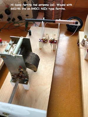
The antenna tuning stage also uses the same ferrite material but in the rod / bar form. I wound a low-end as well as a high-end coil for the tuner using the same high-count Litz as on the big trap coil. The low-end coil is wound on a bundle of three rods while the high-end coil uses a single rod.

Antenna tuner

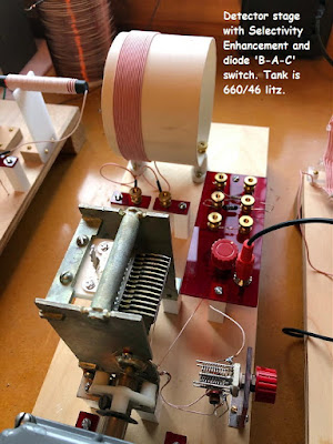
The detector stage uses another Litz coil with this one being solenoid-wound on a 4" diameter form. Both the antenna tuner and the detector use excellent quality hi-Q ceramic insulated air variable capacitors (18-360 pfd). All components that handle RF are insulated from the plywood bases in order to reduce losses. Moving a capacitor from the plywood to the insulated standoffs makes a noticeable difference, something learned the hard way years ago but actually measured while using the new radio.

Detector stage
 

The detector also has provisions for comparing various diodes as not all diodes are created equal ... not even all diodes with the same number! When testing and comparing diodes of the same type such as the popular 1N34 germanium, every once in awhile one of them will turn out to be noticeably more sensitive than the others. In my built-in B-A-C diode test module, the hottest diode is always mounted in middle-position A, making it easy to quickly compare by switching to the left for B or to the right for C. So far the best one I have found is the vintage Russian D18 germanium diode but an old 1N34 removed years ago from a 1950s-era Heathkit has given it a good run for the money! I've still several hundreds of early germanium diodes, pulled from old diode matrix boards years ago, to test against the D18 as well as numerous Schottky diodes.

Also on board the detector module is a Selectivity Enhancement Circuit (SEC) that increases selectivity by unloading some of the diode's effect on the detector coil, similarly to tapping the diode further down the tank coil. It uses a small butterfly capacitor seen to the right of the main tuning capacitor in the photo above. I found it extremely effective when needed and is well worth the addition to a high-performance tuner.

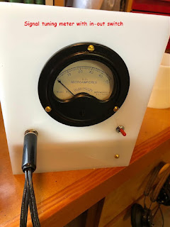
The detector stage is followed by an impedance-matching transformer for the sound-powered headphones. This stage also houses a 50uA meter to measure diode current / signal strength levels.


The meter can be switch-bypassed to prevent needle-bounce on stronger signals. It is particularly helpful when using the traps to null a signal to the minimum level.


The three traps utilized have been very effective in eliminating what I had originally perceived as an impossible DXing situation.

Here are the daytime-power signal strengths of my 15 line-of-site blowtorch stations that, without trapping, very effectively block most sections of the band. Anything over 50uA is ear shattering and problematic, usually requiring the use of all 3 traps:

             KVRI 1600 50uA
             KRPI 1550 100uA
             CJVB 1470 40uA
             CFTE 1410 350uA
             CHMB 1320 100uA
             CJRJ 1200 400uA
             CKWX 1130 300uA
             CKST 1040 90uA
             CKNW 980 150uA
             KGMI 790 100uA
             CHMJ 730 450uA
             CBU 690 650uA
             CISL 650 200uA
             CKSP 600 100uA
             KARI 550 100uA

Overall I was very pleased and surprised at the good performance of the new radio. During the contest period I identified and logged 92 unique stations in 16 states / provinces. More than one station was logged on 9 different frequencies as the propagation varied from night to night.

Highlights of the DX Contest were hearing WHAS in Kentucky (2,007 miles), WJR in Michigan (1,970 miles), KXEL in Iowa (1,556 miles), WCCO in Minnesota (1,423 miles) and CBW-990 in Winnipeg, smack up beside local blowtorch CKNW-980! Additionally, hearing Washington state 250 watter KFLD-870 and 250 watt KWBY-940 in Oregon were great surprises.


I found the use of a spotter radio (Sony ICF-2010) to be very useful in locating signals to target and to zero-beat with an RF signal generator. The generator’s tone-modulated signal can then be tuned in and the xtal radio and antenna / detector stages optimized. 

From here, any pest signals are then tuned to and individually nulled using the traps while watching the signal meter. Antenna and detector stages are then re-tweaked before disabling the generator and listening for the desired signal. 

Often it is heard immediately following the above tuning procedures but if not, monitoring the frequency for several minutes often allows time for the weak signal to fade up to audible levels. 

Comparing programming audio with what is heard on the spotter radio will confirm hearing the correct signal as will comparing audio to the station’s own live-feed on the internet.


Due to the larger and much better antenna (inverted-L 70’ x 100’) on the crystal radio, I would often hear good audible signals on it and not on the spotter (something that I found surprising) so often times it was productive to just tune around the band on the crystal radio, tweaking stages as required.


I’m looking forward to further improvements of the tuner as well as to the next DX Contest whenever that will be scheduled ... hopefully you can join in as well!

 
CONTEST LOG (pests in red)

                    FREQ UTC    STN    LOCATION    MI      

540    3:50    CBK    Watrous, SK    764      
550    1:04    KARI    Blaine, WA    25      
560    1:30    KPQ    Wenatchee, WA    168      
570    3:45    KVI    Seattle, WA    107      
580    3:42    KIDO    Nampa, ID    492      
600    1:17    CKSP    Vancouver, BC    32      
610    4:15    KONA    Kennewick, WA    271      
620    1:22    KPOJ    Portland, OR    241      
630    3:40    CHED    Edmonton, AB    530      
630    21:10   KCIS    Edmonds, WA    87      
650    1:05    CISL    Richmond, BC    24      
660    3:30    CFFR    Calgary, AB    693      
660    21:23   KAPS    Mt. Vernon, WA    52      
670    3:25    KBOI    Boise, ID    807      
690    1:06    CBU    Vancouver, BC    19      
710    3:21    KIRO    Seattle, WA    108      
730    1:02    CHMJ    Vancouver, BC    22      
750    3:55    KXTG    Portland, OR    243      
760    4:01    WJR    Detroit, MI    1970      
770    3:17    KATL    Miles City, MT    831      
780    4:00    KKOH    Reno, NV    658      
790    1:07    KGMI    Bellingham, WA    39      
810    4:05    KGO    San Francisco, CA    786      
820    1:59    KGNW    Seattle, WA    106      
830    2:20    WCCO    Minneapolis, MN    1423      
840    4:10    CFCW    Camrose, AB    530      
840    4:00    WHAS    Louisville, KY    2007      
850    4:20    KOA    Denver, CO    1118      
850    1:12    KHHO    Seattle, WA    121      
860    3:48    CBKF    Saskatoon, SK    758      
860    1:04    KPAM    Troutdale, OR    226      
870    4:30    KFLD    Pasco, WA    266      
880    1:17    KIXI    Seattle, WA    102      
890    4:35    CJDC    Dawson Creek, BC    494      
900    4:38    CKBI    Prince Albert, SK    810      
910    4:40    CKDQ    Drumheller, AB    468      
920    4:42    KXLY    Spokane, WA    285      
930    1:50    KBAI    Bellingham, WA    37      
940    4:45    CJGX    Yorkton, SK    940      
940    0:58    KWBY    Woodburn, OR    256      
950    4:50    KJR    Seattle, WA    106      
960    4:52    CFAC    Calgary, AB    444      
970    4:55    KBUL    Billings, MT    722      
980    1:08    CKNW    New Westminster, BC    32      
990    4:58    CBW    Winnipeg, MB    1156      
1000  3:45    KOMO    Seattle, WA    105      
1010  4:59    CBR    Calgary, AB    453      
1020  0:54    KWIQ    Moses Lake, WA    216      
1030  5:06    KTWO    Casper, WY    918      
1040  1:09    CKST    Vancouver, BC    23      
1050  5:10    CJNB    N Battleford, SK    707      
1060  5:07    CKMX    Calgary, AB    441      
1070  5:10    cfax    Victoria, BC    33      
1080  0:33    KFXX    Portland, OR    232      
1090  1:40    KFNQ    Seattle, WA    109      
1100  3:55    KFAX    San Francisco, CA    779      
1110  5:15    KRPA    Oak Harbor, WA    48      
1120  0:48    KPNW    Eugene, OR    340      
1130  1:10    CKWX    Vancouver, BC    22      
1140  5:20    CHRB    High River, AB    443      
1150  5:50    CKFR    Kelowna, BC    185      
1160  5:53    KSL    Salt Lake Cty, UT    781      
1170  1:11    KPUG    Bellingham, WA    39      
1180  5:09    KOFI    Kalispell, MT    416      
1190  5:55    KEX    Portland, OR    241      
1200  1:12    CJRJ    Vancouver, BC    23      
1260  5:58    CFRN    Edmonton, AB    522      
1290  6:00    KUMA    Pendleton, OR    306      
1290  6:00    KGVO    Missoula, MT    449      
1320  1:13    CHMB    Vancouver, BC    23      
1360  6:12    KKMO    Tacoma, WA    115      
1370  4:32    KXTL    Butte, MT    535      
1380  6:16    KRKO    Everett, WA    88      
1410  1:14    CFTE    Vancouver, BC    22      
1460  1:55    KUTI    Yakima, WA    207      
1470  1:15    CJVB    Vancouver, BC    25      
1480  1:20    KBMS    Vancouver, WA    227      
1520  1:05    KKXA    Snohomish, WA    88      
1520  1:13    KQRR    Oregon City, OR    241      
1530  4:30    KFBK    Sacramento, CA    698      
1540  1:50    KXPA    Bellvue, WA    102      
1540  4:46    KXEL    Waterloo, IA    1556      
1550  1:16    KRPI    Ferndale, WA    31      
1560  1:14    KVAN    Burbank, WA    272      
1580  6:25    KGAL    Lebanon, OR    297      
1590  1:22    KLFE    Seattle, WA    91      
1600  1:00    KVRI    Blaine, WA    25      
1620  1:30    KYIZ    Renton, WA    111      
1640  6:45    KDZR    Lake Oswego, OR    239      
1660  0:56    KBRE    Merced, CA    812      
1680  1:35    KNTS    Seattle, WA    91      
1690  0:53    KFSG    Roseville, CA    705