Showing posts with label optical. Show all posts

Saturday, 10 October 2015

More VE7 Lightwave Activity

Two more VE7's are well on their way to getting in on the lightwave fun in the Vancouver lower mainland region. Toby, VE7CNF, and Mark, VA7MM, are constructing stations similar to the ones built by myself and Markus, VE7CA.

Toby and Mark live close enough that a clear-air scatter QSO between them might also be a possibility. Having another near-by amateur, or even in the same city, is a great source of motivation ... not to mention having someone else to actually talk to, once the system has been built.

Except for the LED focusing sled, Toby's fine-looking transmitter box and LED driver / modulator, are now complete. The receiver is next on the list. I believe this will use one of the inexpensive ($5) fresnels lenses, purchased locally at Princess Auto, that seems to work very well for the price.


photos courtesy VE7CNF
At this pace, perhaps a four-way VE7 lightwave QSO will soon be in the making!

Thursday, 8 October 2015

Clear Air Scatter Tests On 458THz

After patiently waiting for the bright moon to clear the early evening skies, I was finally able to venture out for my first clear-air scatter test this past Sunday night. I had plotted the path on my Mayne Island map and determined bearings as best I could, but the path was going to be very tight. If the path plan was right, my signal should just clear the high beachfront bluffs at the chosen sea-level receiving site.

After carefully aiming the light, I set off for the receive site at around 7:45PM and was all set up with the new lightwave receiver about 30 minutes later. The site appeared fairly quiet and the Argo screen confirmed that there was little QRN coming from the local houses up on the bluff. I listened for over an hour, trying various slow changes in pointing ... varying the azimuth a few degrees at a time, and then the elevation. Unfortunately not the slightest indication of my ~549Hz tone was seen. I was confident that the system was working as several strobes were heard from distant aircraft (near Vancouver), as their flashing lamps skimmed the edge of the far treeline.


It seems likely that either my aiming or bearing calculations (or both) were off and that the signal was probably slightly to the west of me, with the bluff blocking any hope of reception ... I knew it was going to be close but was hoping for a little luck.


I left the transmitter outside overnight (it was set up two properties to the SE) and decided to try a second shot on Monday night. This path, although shorter by a mile, would require the signal to pass over two high hills ... the first topping out at 667' and the second at 567'. The overall direct-path distance was 1.7 miles (2.7 km). A cross-section of the signal path is shown below as it hugged the edges a little lower than the peaks:

courtesy: http://www.heywhatsthat.com/profiler.html

I have been using a 'compass' app on my I-Pad to determine directions when aligning the transmitter and receiver setups. I'm not 100% convinced of its accuracy at all times, as readings can sometimes be a bit flaky. Before doing any more testing, I'll need to solve this, either with a better app or with a real compass.

The transmitter was set up just before darkness, pointing right at the edge of the treeline along the 667' ridge and elevated at a 28 degree takeoff angle. The deep-red, 640mw LED, was switched-on just before departure at around 8:30PM.


It didn't take long to get set up in the back of the CRV, with the receiver temporarily set in no particular direction and plugged into the computer.


When Argo came to life, I went to the front of the car to grab the I-Pad so that the receiver could be aligned but was surprised to see a bright line at 549Hz when I came back! It seems that my 'rough' placement of the receiver was spot-on, and not exactly where I had originally intended. In fact, there appeared to be about a 10 degree error in where I had planned to point. I later traced the error to my path drawn on the paper map as it was difficult to determine my exact receiving location on the older map, which didn't show the new road where I had set up on.

Monday night's path
I was eventually able to fine-tune the aiming and hone-in on the best spot but was surprised that there was a broader degree of acceptance in both azimuth and altitude. At around 8 degrees of elevation, and although I was pointing well into the nearby trees, the signal was still observable with just tiny patchs of sky poking through behind the trees. At 10 degrees I was above the trees, with a solid signal. Surprisingly, the signal was not lost until pointing past ~ 15 degrees ... I had expected sharper pointing.

With the strength of signals recovered on this path, two-way communication could have easily been established on any of the CW QRSS modes ... if quieter, probably on normal audible CW. Signal strength indicated that there was still plenty 'left in the bucket' for greater distance paths, probably much further than I am able to test here on the island.

This was the first thing I saw, at the QRSS60 mode in Argo ... a fairly narrow passband and a ~25+ db dig into the noise.


Backing off to a wider bandpass (less sensitive) but faster QRSS10 mode showed the signal still very apparent:


The almost 'real time' QRSS3 mode, although showing a much weaker signal, indicated that the signal would have been almost audible had it not been for the high level of background noise at this site. Don't confuse the lightwave signal with the much stronger 9th harmonic of 60Hz on 540Hz!


The ferry terminal was just down the hill about 1/2 mile and with several kilowatts of spectrum-polluting 60Hz sodium vapor lighting, the cloudy skies were a sea of bright-pink. There was a high level of audible hum in the phones, right from the start, that unfortunately, masked any hope of an audible detection. The waterfall screen capture shown below, illustrates the massive QRM at this otherwise nice site!


The night was not going to be complete without a strobe signature, captured on Argo from a high passing jet aircraft:

strobes

All-in-all, it was a very successful outing, considering the obstructed path and the $5 fresnel lens used in the portable receiver! I've examined the island map for any other possibilities and there are not many suitable candidates. I had hoped for one other possibility towards the west, which would stretch the path by almost another mile, but I'm not really sure that I can get a clear shot without hitting the very close treeline at this end.

I think the next round of testing will be in the other direction ... across Georgia Strait, with John, VE7BDQ, who has expressed interest in doing some deep overnight Argo searches for my signal in the clouds.

I'm not sure which mode would offer the best chance ... 'clear air scatter' or 'cloudbounce'. John has a very good receiver, with a slightly larger and better-quality fresnel than the one used in these tests. Working from his suburban backyard, directly across the strait at 13 miles (21 km) distant, his direct path to me is somewhat obstructed and will require an elevation angle of around 30 degrees at his end. I think, ideally, we would both like to be skimming just above the ocean, with only a slight elevation. A lower and less obstructed shot from his yard would mean an oblique path so this also remains a possibility. We will play with what we have and hope for the best ... even just a trace of signal would be a measured success.

I think that a non-line-of-sight (NLOS) contact would make an exciting challenge and a great project for two amateurs living in the same city or town, and ... you really don't even need a ticket!

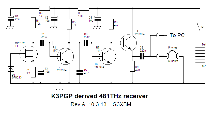
For more technical details on the equipment used in this test, see "A West Coast Lightwave Project" describing the activities between here and Markus, VE7CA. We have just learned that this article will be published in the 2016 Radio Amateur's Handbook ... hopefully inspiring  more new lightwave activity!

Wednesday, 23 September 2015

Lightwave Scatter Planning


Over the past few days I've been trying to figure out some possible pathways that might be covered when transmitting from home.


The only real directions that I can go any distances are towards the southwest and to the southeast because of two large hills (500' and 900') to the south.

courtesy: https://www.google.ca/maps
courtesy: http://www.jeffstopos.com/

The challenge will be to put a signal over this 500' hill, about 1.5 km to the south ... I'll need to go around it on either side or over the top. Going around it at its edges will allow me to keep the light beam on a fairly low angle.

The main obstacle is my lot ... it is heavily treed in these directions and aiming would have to be too high of an angle to get over the trees. I do however, have one small gap between the trees which has turned out to be close to the right bearing (220 degrees) for the southwest test. For this, I can set the transmitter on my back sundeck and shoot through the gap without bothering anyone. For the southeast shot, or one over the top,of the hill, I'll need to move the transmitter two lots to the east of me, and use the neighbour's clear view of the hill.


This should work out OK, as the neighbour spends the winter in Boston and the house is vacant ... but the outside power sockets are alive. This path though, has me shooting across a small bay and above several houses. Most are summer residents only but there are a couple that are permanent. I'll need to contact them and give them a 'heads-up' before I run any tests, so they don't call the RCMP!

The June 2014 edition of Radcom has an inspiring article by G3XBM, "Over The Horizon At 481THz", where Roger describes his early clear air scatter tests and excellent results over an 8.5 km path. This is a very impressive distance considering the small LED transmitter and 4" magnifying-glass lenses used.

Unfortunately, the distances here, on both paths, are not very much ... about 5 km. I'm  fairly limited to how far I can go here on the island. I'd be very happy to cover this comparatively short distance and a lot will depend on being able to keep a low enough angle and still get over the hill.

With the right weather, I may start as one reader has suggested, with a short almost vertical incidence shot and set up a few blocks away to test out the system.

Sunday, 13 September 2015

Portable Lightwave Receiver Progress


Yesterday, between dabbling in the Arkansas State QSO Party on CW, I manufactured and assembled the PCB for the new 'portable' lightwave receiver. When building PCBs, I use the printer-toner method, after drawing the design with MS Paint. Compared to some of the freeware PCB design software now available it is fairly crude, but it more than meets my needs and could even work for designing SMD boards if needed. I've also made the switch from using the messy and corrosive Ferric Chloride etchant to a weak solution of Hydrogen Peroxide and Muriatic acid. The latter seems so much cleaner, faster and overall produces a better-etched board. Boards can be completely etched in around three minutes, compared to the much longer Ferric Chloride.


I chose to use the same receiver circuit as the one in my main system, garnered from the design shown in Roger's, (G3XBM) blog. If you have an interest in getting started in lightwave experimenting, you will find Roger's blog of his lightwave adventures to be both informative and inspiring.

courtesy: http://g3xbm-qrp.blogspot.ca

As before, I made a couple of minor changes to the receiver, substituting a BPW34 optical pin diode for the one shown as well as subbing a 2N5457 JFET for the MPF102. In addition, 2N5089s were substituted for the 2N3904s. The newer JFET is lower in noise as are the higher gain 5089s. In all likelihood, the differences are only minor but I like to think that every little bit helps when all system-losses are considered.


Note that it is important to make the connection between the diode and the JFET's gate lead 'floating' in the air as any contact with the PCB could introduce unwanted loses at this point.


As in my original receiver, a locking split-shaft, removed from a junk box potentiometer, was mounted to the back side of receiver box. This will allow the receiver box and its pin-diode to be aligned forward and backward for focus and then locked. Once built, the focusing carriage will allow the receiver to move laterally, left to right as well as vertically, up and down. Positioning the optical diode at the exact focal point of the lens and maintaining this position is crucial. The finished carriage, will look similar to this one, used in my main system's receiver and transmitter box.


So it's on to the plywood receiver box and then the focusing carriage. It will be interesting to see how my $5 fresnel lens page-reader, purchased from Princess Auto, compares with the slightly larger (and probably better) lens in the main system's receiver.

Sunday, 24 August 2014

On Making Nanowaves - Part 6

After several weeks of reading, planning and homebrewing, both the transmitter and the receiver boxes were finally finished....at both ends of the path!


After the transmitter and the receiver had been accurately focused (the receiver's photodiode at the fresnel's focal point and the transmitter's secondary lens properly positioned) both enclosures were screwed together and mounted on a tripod.


Markus, VE7CA, had checked-out a suitable location not far from his home QTH on the road to one of the local ski-hills. This gave him an unobstructed view to my location on Mayne Island, about 54km to the southwest. I had planned to set up in my front yard, about 15' above sea level and on the eastern shoreline with a direct shot to Markus.

Even though we were using LEDs rather than lasers, I still felt somewhat uneasy as our path crossed directly over the runways at Vancouver International (around the path midpoint) as well as the main ferry lane between Vancouver Island and the B.C. mainland. Considering the distances involved, I probably need not have worried as the light, although bright, would cause no physical harm other than possible momentary distraction or curiosity. If one of the ferries had been approaching the path, I had planned to shut down until it had passed as it would have been hard to convince authorities that the light really was not a laser, before they carted me away!

After waiting for the usual winter B.C. rain to subside, we finally had a promising evening shaping up, although somewhat cold. Markus, accompanied by Jim, VE7BKX, loaded his vehicle and headed for the mountains. With neither of us having 2m portable radios, we somewhat guiltily reverted to cellphones to announce setting-up status.

VE7CA/7
Shortly before dark, I aligned my light boxes to point at what I was pretty sure was Markus's location and turned on my FSK beacon.... the bearing was taken from Google Maps and alignment aided by my I-Pad's Commander Compass Lite app. The plan was for Markus to sweep until he (hopefully) heard me and then turn on his beacon so that we could then both tweak our final alignments.

Almost immediately I heard his beacon signal although there was no visible sign of his light.

Before final alignment I made a quick recording of his signal.

Neither if us had any real idea of what type of signal strength to expect and we were both very surprised to hear how strong the signals were. Once we had both aligned and our lights were now visible, we switched to CW mode and proceeded to work each other in typical QSO mode.

Hear is a recording of Markus sending my RST report.

Signal reports as well as grid squares were exchanged just to make everything 'official'. We then settled into a nice twenty-minute ragchew until the cold winter air took its toll on our fingers forcing us both to close down and pack up for the night.

Markus grabbed a short cellphone video from his end which shows the still fairly bright twilight skies and the LED signal source:


Earlier, John (VE7BDQ) had made the decision to not build a transmitter as he preferred not to go portable. Both of us were interested in pursuing a possible non-line-of-sight (NLOS) path by using either 'cloudbounce' or 'clear-air scattering' which would allow John to set up in his backyard. The path between us is much shorter than the VE7CA/7 path as can be seen in the map below:

Courtesy: https://maps.google.ca/
To date we have made one test at this mode, trying various takeoff angles at my end, but cloud conditions were not optimal, and as yet, I am not totally certain of what type and height of cloud would be best. Perhaps we should be looking for the typical very light fog that often forms over Georgia Strait for enhanced water molecule scattering? As well, I think our best chances for success would be the slow speed QRSS mode, possibly QRSS3 or QRSS10 which could offer as much as 20db signal gain over normal speed CW.

For one-way beaconing, I plan to add a more accurate crystal-controlled tone module so that my CW signal's frequency is precisely known and can be watched for in the very narrow bandwidth window of Argo or Spectran over a given period of time. Even at these slower speeds, QSOs exchanging the minimum required information can still be made relatively quickly. Hopefully any reception at all of my signal at John's location will excite him into building a transmitter as well. Completing a two-way contact using the NLOS mode would be a very interesting challenge.

In the meantime, Markus and I have been seeking out possible new locations for his remote work, using "HeyWhat'sThat Path Profiler" web site. This site quickly indicates the distance and headings between any two points and draws a geographic contour of the path showing any obstructions.

Courtesy: http://www.heywhatsthat.com/profiler.html

Markus hopes to get out to one such favourable location in the Fraser Valley mountains, before the weather turns nasty once again.

If there is anyone in the Vancouver lower mainland region that might be interested in building a lightwave station to join us in the fun, please do not hesitate to make contact with any of us...we would love to hear from you!


If you are a member of the Radio Amateur's of Canada (RAC) and receive their 'TCA' journal, please watch for our upcoming article in September's issue..."A West Coast Lightwave Project".

Friday, 22 August 2014

On Making Nanowaves - Part 5

With the fresnels in hand, a pair of plywood box enclosures were built...one for the receiver and one for the transmitter. Eventually they would be coupled together so that both would be pointing at the same distant spot.


The next step was to use John's design to mount the receiver and transmitter modules so they could be locked into position once aligned properly. His system used the 1/4" split shaft locking mechanism removed from an old Allen-Bradley potentiometer to hold a short length of rod fastened to the module's case.


This allowed the shaft to be moved forward and backward for focus while the slot in the mounting plate allowed for vertical centering. The plate mounting mechanism itself allowed for lateral centering. This system allowed for the locking of the receiver's photodiode at the exact focal point of the fresnel lens.The same scheme was employed for the transmitter's LED as well, since accurate focusing was critical there also.


In order to focus as much of the LED's light onto the primary fresnel lens, a small inexpensive (secondary) collimating lens was required. This assured that the fresnel was properly illuminated out to its edges and no further. Any light spilling over the edges of the fresnel would just be wasted.


Our particular fresnel had an effective aperture of 260mm and a focal length of 200mm, producing an F-number (f/D ratio) of .76.... Clint suggested that our collimating lens should have an F-number of ~ 1 - 1.2 and be a PMN (Positive MeNiscus) type and that we hedge our bets by trying lenses above and below that value. Ideally the collimator should be at least 25mm in diameter for ease of mounting and, when perfectly illuminating the fresnel, be as close to the LED as possible, if not touching it. Just placing a less than ideal secondary too close to the LED would end up over-illuminating the fresnel, while having it too far away would under-illuminate it.

Accordingly, four small glass collimating lens of various F-numbers were purchased from Surplus Shed at around $4 each. Each lens was then mounted on a drilled-out piece of PCB material using 'JB Weld'.


Once cleaned-up, the lens board was then positioned directly over the center of the LED on a machine-screw carriage mount. The carriage allowed the lens to be locked into position once it was correctly positioned. All four lenses were tested to see which one would correctly illuminate the fresnel while still being as close to the LED as possible.


The eventual winning secondary lens was #L10016 (.9 f/D) which allowed for a sharp and fully-illuminated fresnel while being just a few millimeters above the LED.


The next step was to adjust the entire LED and secondary carriage for the sharpest focus on a distant flat surface. This was done over a distance of about 200' and was a fairly fine adjustment.


Once done, it was actually possible to see the two fine wires connecting to the LED die on the distant projected image.


With the final focusing taken care of, the tone modulator and MOSFET LED driver were installed. This used an IRF540 switching FET, driven by the digital tone signal to control the current through the LED.


All we could do now was patiently wait for a nice clear evening to put the system to work.

Wednesday, 20 August 2014

On Making Nanowaves - Part 4

Researching suitable LEDs for our lightwave project forced me, once again, to the bottom of the learning curve. Like the variety of photodiodes being used in simple lightwave systems, there were a myriad of LEDs experimentally lighting up the skies both in the UK and in the U.S.

It seemed that the present flavor-of-the-day in terms of LEDs was the Luxeon III, a 3W / 1.4A device being produced by Phillips.....or rather.....was being produced. Apparently our new found interest in lightwave communications had been coincidental with the retirement of this popular LED and all stock had been depleted! Although still available in some wavelengths, there were none in the desired 'deep red' portion of the spectrum that we had chosen for our system.

Courtesy: http://www.luxeonstar.com/luxeon-rebel-leds


All was not lost however as a 'replacement', largely untested by the lightwave community, spec'd-out at a lower power but with a somewhat more efficient design. The new device was the Luxeon 'Red Rebel' and rated at 700ma. ....apparently no slouch at all.


I had also been watching the various offerings available on e-bay which provided a number of tantalizingly inexpensive options. Many of the LEDs from China appeared to offer good promise and may well be good performers, but most appeared to be lower-quality knock-offs of the name-brand models.

These higher-powered LEDs, on close examination, usually contained two or more separate LED die behind the lens. A single light source is required to achieve maximum focusing / lens illumination efficiency and although tempting, should probably be avoided. 'Safe' names to look for include Philips, Osram and Luminus and often, bargains can be found on e-bay when NOS is being disposed of.

Like most 'power' LEDs, the Rebel needs to be mounted on a heatsink otherwise catastrophic destruction would be immediate. The usual method of heatsinking is to attach the LED (by solder or adhesive) to a copper star-shaped interface which is then fastened to a small heatsink.


Courtesy: http://www.luxeonstar.com
 
The interfaces can be purchased separately but soldering the LED can be challenging without overheating it. They can also be fastened with JB Weld and enough pressure to ensure a firm bond without damaging the LED. An easier alternative is to procure the LED already mounted on the interface as shown here.


Once adequately heat-sunk, voltage can be applied to the LED after taking measures to limit the current to safe levels. Although these LEDs are very small, they emit an exceptionally bright light and must be treated with care. The Rebel is shown here, shortly after first applying voltage. The current in this test was just 100ma. Although they are rated at 700ma, I have run this one up to 1A without failure but it is normally run at the rated current.

Luxeon Red Rebel at 100ma.
The next task was to tackle the 'antenna' which, in a lightwave system, is the lens. Many of the UK amateurs were having good results with inexpensive 4"-5" magnifiers mounted inside ABS or PVC tubing. The remainder, and those in the U.S., were using plastic Fresnel lenses mounted in homebuilt plywood boxes of various designs. Clint's (KA7OEI) website contains a vast amount of valuable hands-on info describing the latter and we chose to go via that route.

Like the large variety of both photodiode and LED selections, fresnels were no different. Once again there was a lot of information to digest while learning about the various types. Eventually, John, Markus and myself each purchased two plastic fresnel lenses from 3DLens in Taiwan. One would be used in the receiver box while the other was for the transmitter. These were 26cm square lenses, model A260.

Unfortunately I no longer see these particular lenses being offered....hopefully it is only a momentary depletion of stock. There are many different sizes and types of fresnels out there....some if them perfect for this type of use and others not so good, so think carefully before buying anything and know what you are getting. Studying Clint's pages regarding fresnels will help immensely.

Things to pay attention to are the focal length and groove 'pitch'. For a typical 10"-12" lens, look for something around 10-12" focal length, otherwise the mounting enclosure will get too deep and awkward to handle. Front surface 'groove pitch' should not be too fine...something around .5mm is good but our finer (.2mm) seemed to work well also.

Now that the LED had been mounted and the fresnel lenses were in hand, the next task would involve the focusing mechanism and alignment. Thankfully John had devised a smart method for mounting and adjusting focus a few weeks earlier, when we were still working on receivers.....

Saturday, 16 August 2014

On Making Nanowaves - Part 3

Having studied many of the receiving systems being used by others, it seemed that designs ran from the 'very simple' to the 'very sophisticated'. Once again I looked to Roger's experimental work involving receivers since the one he had been using had evolved over a period of several months and several tweaks. The design that he used was an adaptation of the original low-noise PIN diode laser receiver designed several years ago by K3PGP and shown here on K3PGP's Experimenter's Corner.

Roger's adaptation, shown below, appeared to be getting excellent results when used in his over-the-horizon clear air scattering tests.


Although Markus, John and myself all built the same design, it is interesting to see the end results, as each used a different construction method.

John chose to use perfboard and point to point-to-point wiring:

VE7BDQ's Perfboard RX
I built mine on a PCB....

VE7SL's PCB RX
...and Markus used 'dead-bug', also known as 'ugly construction' style, the preferred method of most scratch-build homebrewers:

VE7CA's Dead-Bug Style RX
I made a couple of small changes and used a 2n5457 JFET in place of the MPF102 as well as some 2n5089's in place of the 2n3904's. I think Markus swapped JFETs as well and used 2n4401's for the bipolars, while John built a stock version of the receiver.


All of us used the Osram BPW34 PIN diode for the detector after having it recommended by Clint in e-mail 'detector discussions' as being a good performer . It is still readily available from the usual places, at around eighty-cents.

BPW34 Spectral Range
The BPW34 turns out to be sensitive over a fairly wide range of frequencies. At our frequency of interest (deep red) at the edge of the IR range, the detector is operating at about 65% of its peak performance which is lower and well into the IR range.


Many silicon PIN photodiode detectors are available with filters that let them achieve maximum sensitivity at the lower IR range while blocking the unwanted higher frequency visible light sources. Such is the case with this one, available as the BPW34FA. If you wanted to run an all IR system, reducing visible light QRM, this detector might be a better bet.


BPW34FA Spectral Range


When it comes to diode detectors, there are always  new challengers appearing in the marketplace. There are still many opportunities for experimenting when it comes to optimizing the front-end of your receiver.


When coupled with its focusing lens in the final stage of construction, the receivers are amazingly sensitive. Even the slightest hint of a light source, often invisible by eye, would produce a response from the system....even starlight!

One of the first sounds detected was a low-pitched and repetitive 'thump-thump' which turned out to be the wingtip strobe lighting of jet aircraft activity approaching and departing Vancouver International Airport. After several nights of listening it was apparent that the strobe lighting could be detected from at least 70 miles out and from aircraft still above 10,000'. Panning over to the runway (about 25 miles away), I could often detect the strobes from departing aircraft even though they had not appeared above my sea-level horizon. Eventually I would see them rise above the horizon, about a minute after hearing them on the runway while on their takeoff roll. I suspect the propagation mode would be a form of clear-air scatter since there was no direct line-of-sight to the signal source when initially heard.

Panning the receiver slowly along the many miles of coastal mainland, on the other side of Georgia Strait, revealed many signals, most of them with different audio signatures. Some sounded rough and buzzy, like an unfiltered CW note, while others were T9 and very clean. Most had different repetition rates resembling radar sweep speeds but, once again, most sources were not visible to my eye...nor were they located when scanning the signal source with binoculars. I suspect that most signals were from various fixed lighting installations either strobe lighting or area flood lighting. Some targets appeared to be slowly moving and were found to be coming from tankers and container ships travelling along the far coast line. Hearing so many of these modulated lightwave signals was certainly an interesting experience and something I had not really expected. Even individual stars would produce a detectable 'hum' as the receiver/lens combination was aimed directly at them.

My one and only daylight test revealed extremely high levels of hum from the bright sky and, no doubt, front end overload desensitising....but the sudden sound of a buzzing bee in the headphones turned out to be just that, as the reflected light from its wings was being modulated by the rapid flap-rate....all very eye-opening to me and totally unexpected.

Here are some recent audio recordings made during a period of heavy cloud cover over Georgia Strait. All are on the far mainland coast or further inland and most sources were not visible to my eye.


    I think such a system would make a wonderful 'science-fair' project for a budding student, complete with recordings....but perhaps it has all been done before!

    For a very in-depth study of various current RX designs, see the Optical Receivers page of KA7OEI.

    With all three receivers working well, the transmitters would be next....

    Thursday, 14 August 2014

    On Making Nanowaves - Part 2

    Now it seemed that up until just a few years ago, most amateur lightwave work had been done using lasers. The UK boys, as well as others, were now using LEDs, whose technology had made huge strides in recent years. The 'non- coherence' of LED light, unlike lasers, offered a distinct advantage when used for communications. Fading and signal dropout during periods of poor visibility were significantly reduced with the non-coherent LEDs when compared with laser light's 'all or nothing' characteristics.


    Courtesy: KA7OEI
     
    As well, the thought of using lasers was somewhat scary in view of the growing amount of negative publicity from frequent reports of irresponsible use....combined with the fact that my path to VE7CA had to cross Vancouver International Airport!


    Shining just a low-powered laser across this region was not something that I felt even remotely comfortable about doing. I felt much better about the project the more I learnt about LED's and of the good results being had by other experimenters.


    Another exceptionally good source of valuable information (and probably the best on the Internet) is the 'optical' page site of Clint Turner, KA7OEI. Clint is an exceptionally gifted engineer-experimenter and is extremely generous in sharing his knowledge with others. As our local project developed over the course of many weeks, we exchanged several e-mails. My numerous questions would always result in very long detailed answers...and precise explanations for the reasons behind the answer or suggestions.

    Clint Turner, KA7OEI

    Just name any radio-related activity and Clint seems to be not only involved in it but has excelled in it. His willingness to share with others is just another example of why our hobby is so enjoyable!


    While still deciding on receiver / transmitter designs, I built a small audio tone generator that would be needed, no matter what type of transmitter was eventually built. The plan was to have some method of making our signals stand out when searching for them in the noise. A distinctive two-tone FSK alert tone was decided upon as it could easily be built using a pair of 555's or a single 556. The final module allowed for three separate modes...an FSK 'beacon' mode, a keyed 'CW' mode and a short 'dash' mode (less annoying than the 'alert' tones).

    
    Modulator mounted on TX
    Here is a recording of the FSK 'beacon' mode in action.

    
    Courtesy: http://electronic-projects.50webs.com/p1.htm
    The base tone was set at about 600Hz since we preferred the lower tone for CW work.
    No doubt there are other methods of building the FSK alert module but the 556 is simple and worked well.

    For very weak-signal CW work, likely involving slow-speed (QRSS) modes in future 'non-line-of-sight' (NLOS) 'cloudbounce' trials, something with a bit more accuracy such as a crystal oscillator divided-down to audio frequencies would be better. Such a system would be very stable and provide a more precise modulation frequency... necessary for the narrow bandwidth viewing windows required for Argo or similar DSP audio viewers.

    With the tone generator taken care of, the receiver was next on the list.