An e-mail alert from Toby, VE7CNF, on the other side of Georgia Strait, indicated that everything was ready for a two-way test on 2200m and he was looking for his initial contact on the band. Having not been on the band for such a long time, some review of my 'tune-up' procedures were in order as well as the need to burn out the spider webs in my outdoor loading coil.
Since being on 2200m, I had modified my 2200m kilowatt transmitter so that it could also be used on the new 630m band. To change bands from 630m back to 2200m, I needed to swap the frequency-sensitive power divider back to 2200m as well as re-set the DDS frequency.
 |
| 2200m Power Divider |
When modifying the transmitter, three years ago, I had also changed the transmitter's input frequency divider from a 'divide-by-four' to a 'divide-by-two' scheme. My original system on 137KHz started with a DDS frequency in the 5.48MHz range and then was divided by ten before being fed to the transmitter's input where the 548KHz signal was then divided by four. Using a higher DDS frequency allowed for greater frequency resolution at 2200m and allowed for very small frequency adjustments across the band. I would have kept the same system for 630m except that my 'divide-by-ten' chip was not very happy at 18MHz and refused to divide.The newer system now only allows me to move around the band in 4.5Hz steps. It's really not much of a problem as there is presently a minuscule amount of activity in Canada on 2200m, but as previously mentioned, this may change when U.S. amateurs gain access to the band.
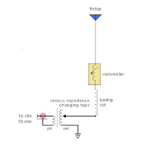
Having sorted out my transmitter problems and confirming that all was well, the next task was to check antenna resonance and impedance matching as it would more than likely not be the same as I had left it. A low-power check using the 'scopematch' indicated that both resonance and impedance were not optimized. Tapping down on the loading coil by one-turn took care of resonance while adjusting the impedance tap in my matching transformer to its lowest value (see matching scheme below) resulted in a near perfect match on the scope.
I'm guessing that the resonance change was due to the recent heavy trimming of the 80' Balsam that supports one end of my 'inverted-L' and large three-wire flatop.
The tree's crown had previously been very dense and some of the branches were almost touching the flatop. The close proximity always made me worry about possible flashover at the antenna ends as voltages here would be several kilovolts. Removing much of the wet green tree branches directly beneath the flatop also likely contributed to the slight change in resonance.
 |
| Impedance Matching Transformer On TV Flyback Cores |
The sked with VE7CNF went smoothly and it was nice to see another new Canadian station taking an interest in the band, along with all of its challenges. Toby's 200W signal was a solid 559 here even with his small antenna system yet to be fully optimized. As well, he was bothered by heavy switching-power supply QRM from a nearby neighbour. Unfortunately, such noise sources seem to be increasing in numbers and are making operation on LF, already a big challenge, even more challenging. Toby has taken up the challenge with enthusiasm and has now had contacts on 2200m well as on 630m, adding to the ranks of active VE7's on LF and ... demonstrating yet again that amateurs can enjoy the LF bands with small 'backyard' antenna systems. Don't let living in the city be a reason to avoid our new LF bands.
Wouldn't it be great to see some activity from our neighbours in VE6 or VE5, both easily workable on both bands from the west coast... maybe you're up to the challenge!


No comments:
Post a Comment