Wednesday 31 December 2014

VK4EBP's NLOS Lightwve Experiments - Part 3

F1AVY's Cloudbounce System


 "Returning to Steve's questions and our general discourse:

..is it (the RX) fairly small and portable...and lensless?

I do have a lens in the RX I now prefer to use - although it happens to be a convex lens from a tabletop magnifier - about 7x12cm giving me a narrow reception beam and a fair bit of gain compared with naked photodiode. There seems to be a general agreement that increasing the size of receiving aperture will capture more light and is the best way to greater gain.

Here I need to qualify gain requirements for my particular applications. I am currently exploring relatively short-distance NLOS paths in urban environments with abundant QRM from city and suburban lights, and this already limits my gain requirements. I developed my own qualitative test of satisfactory sensitivity - by pointing my receiver at individual stars in the sky. If I can hear them twinkle (yes they do twinkle!!!) then I am generally satisfied with the project.

On cloudy nights, pointing the RX into the clouds brings an interesting combination of mains harmonics and general hash from neon lights, clicking pulses from aeroplane lights, sweeping sounds from airport and marine lighthouses. In an environment like this, going to extreme lengths as one would do for very long-range cloudbounce or LOS comms in dark and secluded areas is simply not required and uneconomical. I initially did invest time and money in large receiving boxes with the best components there are, only to find that, unless I moved out into the bush, I could not take a real advantage of the improved performance, and did equally well with smaller and more wieldy portable designs.

"Is the idea, when talking about NLOS, to light up as much sky as possible...and that is why no focusing lenses are employed? Would a focused emitter, as produced by the typical Fresnel lens light box, produce too narrow a beam than desired? It would seem likely that with precise aiming combined with the gain to be had by utilizing fresnels (for example), would produce longer paths??"


There are several separate issues there. One is the implied requirement for a large Fresnel lens in order to obtain a narrow beam. First, how narrow is narrow enough? If we can be satisfied with say +- 5 degrees then there are more wieldy solutions available - most of the high power LEDs now have clip-on small spot lenses awailable separately - usually from third-party manufacturers. These were unheard of until recently. Standard-sized LEDs are available with very narrow radiation pattern, e.g. the SFH4550 at barely +-3 degrees. And one would expect an array of 200+ of them to behave quite like our stacked Yagis, many times over! Hence narrow beam is quite possible even without an external lens.


Osram SFH4550 IR LED

Of course the extremely narrow beams that one would prefer for LOS DX comms would be next to impossible to align in NLOS situation. (Invisible infrared is not a problem in LOS as it can be easily supplemented with e.g. a plain strobe light for alignment purposes.) I find my +-3 degrees array (with similar +-3 deg aperture at receiving end) hard enough to align over the horizon, and it is probably the limit of how narrow one can go to remain practicable in NLOS.

"to light up as much sky as possible..."


It is possible that cloudbounce and obstruction-bounce will develop into separate NLOS techniques, along with atmospheric scatter.  Of course one can think of all of these in some topographies.

I had some success in inter-suburban cloudbounce with high beam elevations at both ends - 30 to 60 degrees. Also with 45 degrees or less elevation with TX and RX about 1km apart side by side and pointing at the same cloud in the distance. Power used around 10-20W, beamwidth +-5 to 10 degrees, red and infrared with similar results (including 950nm). The received signal was just strong enough for telegraphy or qrss, but never near enough for any type of voice modulation. Results were affected by the height of cloud cover necessitating frequent elevation adjustment, and an additional liaison channel on VHF. Signals disappeared entirely as soon as the clouds started producing rain.

I never got any usable results with clear night sky and the TX and (imaginary) RX beams crossing each other at similar elevations. Only at very close distances - the best signals being received with blue and infrared. Presumably Rayleigh scatter with blue. (This raises the possibility of usable atmospheric scatter with UV?)

Only recently I commenced preliminary tests with close-to-ground, low-elevation NLOS and immediately the infrared proved itself to be a clear winner with quite reliable and repetitive results. (Needless to say the signal strengths are marginal compared with direct LOS over similar distance.) Intuitively, one would suspect general scatter and bouncing of nearby objects being the main sources of some of the energy reaching over the horizon, with some contribution perhaps of atmospheric/dust/aerosol scatter.

This adds an additional dimension to your question.. to light up as many objects around the TX(or around RX, or around the obstruction) as possible, or send the focused beam as far as possible? I guess it will very much depend on topography. I can imagine a situation where I would prefer to use a broad floodlight rather than a focused beam - e.g. to illuminate as many as possible of the surrounding tall buildings if transmitting from a ground floor apartment. Or from the foot of a mountain. An opposite rule would apply if it is the receiver that is just behind an obstruction - here a focused TX beam and a broad RX aperture might prove advantageous. And where the main obstruction is midway between TX and TX than the usual narrow-beam configuration would apply at both ends. I think it might be worth trying an infrared TX with interchangeable lenses, and same for the RX...
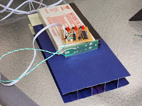
The portable TRX image shows the general view. Most of the electronics is contained in a plastic box and includes an SLA battery, the RX audio bandpass filter, power amp and speaker, and most of the PWM AM TX circuitry except the final LED driver. The DIN socket provides connection to external RX front end TX output drivers and LEDs, usually held together on a tripod. The header socket is for the external microphone connection, and there are switches for power and speaker and a headphone jack. The crudely made corflute box beside it is the RX front end with lens, photodiode and preamp.


The RX detail 01 shows the business end of the photodiode, and the separate lens box (slides in and out for focus adjustment). Detail 02 shows the preamp with interchangeable photodiode modules - SFH213 for visible to 850nm, and the SFH213-FA for 850nm and below.

Multi-wavelength TX 01 (front and back image) includes several groups of fat LEDs (red, blue and 850nm) with matching lenses providing approx. +-5 degrees apertures. Also the PWM driver on 2x CAT4101 in parallel, external high current power connection, intensity control, and a PICAXE-controlled strobe or audio callsign/frequency sweep beacon.The whole assembly connects to the TRX control box (above) and can provide power to it, draw power from it, or have both DC sources in parallel.Enclosure includes a photo tripod mount on the bottom plate, and velcro strips on top to hold the RX front end.


Pocket-sized 10W IR TX is a small holiday project and still work in progress. The 7x LEDs are 2W each SFH4783 with an intrinsically narrow beam of +-10 degrees - quite appreciable for a naked LED of this size and possibly obviating the need for external optics in some applications. My usual CAT4101 drivers are included and capable of providing 2A at 50% duty cycle. Another Picaxe beacon is on the other side of the heatsink, and the voice modulator is still in progress.


The low-power multi-wavelength TX is another one day project, built to compare relative performances of 850 and 950nm IR. Three almost identical beams of red, 850 and 950 are transmitted in sequence with approx 100mA PWM running each diode. Unique CW ID has been coded for each wavelength.


6x SFH213 photodiode with individual preamps - quite a respectable low noise, high sensitivity front-end that works very well without external optics (SFH213 have a +-10 deg intrinsic apertures). A matching array of small fresnel lenses has been built and tested for narrow-beam reception, but a permanent box is yet to be added.. Some of the other gadgets seen in the foreground."


As mentioned earlier, Jan's experiments with NLOS signals utilizing IR is of particular interest to myself as I would like to continue experiments with VE7CA, on the other side of Georgia Strait...hopefully with Markus not having to move to a LOS position, but simply aiming across the Strait in a direct path, from his yard. Using Argo and QRSS3 mode, it will be interesting to see if any signals can be recovered from the cloud bottoms on some overnight runs. 

Don't forget Clint's (KA7OEI) superb Optical Communications / Moduulated Light pages!

Monday 29 December 2014

VK4EBP's NLOS Lightwave Experiments - Part 2


Courtesy: http://www.ledsmagazine.com
Once again, from Jan...

"Visible LEDs and optics: Some of my favourites include the LZ1 and LZ4 series from LedEngin used with matching spot lenses, or thick condenser lenses from old visual projectors. Also various Golden Dragon varieties with matching small plastic spot lenses. Average beam divergence with either configuration is about +-4 degrees. (Happy to provide detailed parts numbers.)

Infrared LEDs: Here we have a some good products from
Vishay (TSHG series), with narrow beam (some go down to +-2 degrees) in the standard 5mm packages and max current of 100mA.


They can make nice pencil-beam arrays in combined series/parallel with 200 or more LEDS and no optics required, at less than 40c per LED. Lots of soldering though :). For the 950nm range (not extensively tested yet) the Vishay TSAL range of LEDs will do nicely.

LED drivers: I found a very neat IC to PWM-drive the LEDs at up to 1A - the CAT4101 from ON Semiconductors.


Usually have two in parallel for a peak of 2A at 50% duty cycle, giving me 1A average to drive the LED string.

At the reciving end I am now using a preamp loosely based on
Clint's no-feedback design with some hum filtering and other post minor post-processing feeding to an audio amp, or to SpectrumLab."
"...tonight I am trying to compare 830nm against 940nm on a 600m short NLOS path. For this, I have just built a small TX with two "naked" LEDs - TSAL6100 (940nm) and TSHG8200 (830nm). Both have identical shapes of their radiation patterns with +-10 degrees. Each mounted inside of a square cross-section black cardboard tube side by side to ultimately give them a very uniform square beam of approx +-4 degrees. Each driven with 440Hz square wave at 100mA with unique morse identifier for each.

There is a third visible LED as well with its own cardboard collimator and morse ID, to serve as aiming tool and a kind of reference.

The purpose is to see whether 940nm would offer additional advantages in NLOS situations, due perhaps to better/different reflection, scatter, refraction or whatever physical processes might be involved.

An additional advantage might be removing my setup further away from visible light pollution. With the growing popularity of LED lighting in both household and the industry we are having a chance of less and less infrared pollution from traditional incandescent or similar sources - and making light comms more practical in urban environments - all with a simple IR filter at the receiving end.


Tonight's tests were not as productive as anticipated, but somewhat educational nevertheless. First of all the receiving location I picked on the map suffered from severe QRM from sodium street lights. I picked strongly all my "big" IR transmitters, but the visible and the "naked" ones were lost in the QRM, if present at all. I returned home, pointed the 150mW TX into nearby bushland and went for a walk. The red light reception vanished immediately after loosing sight of TX, followed quickly by the 940nm with the 830nm persisting the longest up to perhaps 100m - with the beam fired parallel to ground from upper storey into the crowns of the trees. Reception required pointing the receiver slightly up, intersecting the TX beam somewhere in the tree branches.

Briefly - I confirmed what I already knew:
- IR is far superior to visible for NLOS work - indeed visible light is of no use.
- Low elevations and scatter from ground objects is superior to high beam elevations.

A new observation (that I would like to confirm) is that 900+nm is not worth bothering about. It is known that 950nm suffers from greater scatter in atmospheric particles than 850, but this proved to be more of a hindrance than help in NLOS work.

Another practical observation is that the 950nm version of the common SFH213 photodiode (SFH213-FA) works very well in receiving 850nm whilst filtering out lots of the visible pollution (well, perhaps except the sodium lamps!).
I started tonight's session before sunset and got very good NLOS reception of my large IR TXs - in what could be described as quite a bright twilight. (I carry two plug-in front-end modules each with one of the two photodiodes and the input FET.)
Another holiday project - a pocket-sized 10W TX! I found new IR LEDs - SFH4783 - rated at 2W, barely 1.65V of Vf, and intrinsically narrow angle of +-10 degrees. This means no optics, and up to seven of them in series on a small heatsink can be run from a 12V SLA battery.


Osram SFH4783


This reminds me of yet another observation - out of my several large 850nm TXs the best performers are the naked narrow-angle multiple LED arrays - and the one containing 3 high power broad-beam LEDs with spot optics performing the worst. Well the lenses are designed for visible LEDs and I have no guarantee that the material refraction angles and loses are acceptable in the IR range... 

 
Returning to Steve's questions and our general discourse:

..is it (the RX) fairly small and portable...and lensless?   (cont'd)...

Saturday 27 December 2014

VK4EBP's NLOS Lightwave Experiments - Part 1


A recent posting by Jan, VK4EBP, to the Australian Optical DX Group in now defunct Yahoo Groups, has given me renewed hope when it comes to trying some non-line-of-sight (NLOS) lightwave tests. My initial interest in this was spurred by the excellent experimental work undertaken by Roger, G3XBM, all chronicled in great detail in his daily blog postings. A complete chronology of his efforts, filtered for NLOS experiments,  may be found by clicking here... but be warned...his information will have you wanting to break out the soldering iron and trying some of these things for yourself or, better yet, with another nearby amateur.

Jan's posting was chalk-full of useful "hands-on" information and was just what I needed to hear and led to some extensive and interesting conversation, well worth passing on to others. I could summarize Jan's work in point form but I think it is more interesting to let Jan describe it himself.


"Finally some success with over-the-horizon light.
Briefly - several transmitters of several watts each were fired
simultaneously with the beams aimed at the tops of nearby trees, each
transmitter sending unique combination of tones (direct AM).


Osram SFH213-FA
Reception was performed 1km away with the SFH213 photodiode/amp and a
plastic lens approx. 7x12cm. Receiver was aimed towards the TX site and
pointed just over the horizon.

Aural reception of 850nm infrared signals was very good. There was no
trace of TX signals in visible or near-visible spectrum. Signal quality on

850nm was further improved with an infrared-filtered photodiode (SFH213FA, 950nm peak) which provided some attenuation of suburban lights QRM.


My earlier series of experiments over the years was aimed at achieving
NLOS short-range communications in a light-polluted metropolitan
environment. I had limited successes with high-elevation cloudbounce over
several km distance using both red and infrared. Very poor results with
high-elevation scatter in clear air, with blue light appearing the best,
and green and yellow the worst for the purpose. More recent tests
suggested that low elevations with infrared light offer a reliable link,
and today's results seem to confirm that.

More to follow! 10km test tomorrow night. 73 de Jan vk4ebp"

Jan has been testing several different TX emitters / wavelengths, simultaneously, each with a different CW identifier. His path started with a 1km hop through his local residential neighbourhood, with significant obstructions shown below. Later the path was stretched to 10km. His observations involving IR were particularly helpful:
 
1km NLOS Path
"I was firing all transmitters at once, each with either pre-recorded tones or a picaxe generator. The transmitter  in the black box contains: 1x LZ
deep red 10W with condenser lens, 3x1W Golden Dragon 850nm IR LED with
+-4deg spot lenses, and 3x 4W LZ1 blue with +-5 deg spot lenses. Manually
switchable by my very patient family members on request via walkie talkie
from the receiving site. The two multi-LED arrays are approx 10W each in
total, one containing a multitude of +-3 deg SFH4550, and the other
+-10deg some other LEDs - do not remember after many years since building it. The small heatsink block contains 4x LZ1 far red, run at about 8W
total."


"At the NLOS location 1km away I was able to copy all the 850nm TXs and

none of the visible/borderline ones.Last night I tried 10km distance.

The topography is theoretically line-of-sight, but isolated from the receiving site by a thick bushland in nearby park. I was firing the transmitters about 3 degrees above what
would be line of sight, thus having about half the beam into the air and

another half scattered in the tree tops near the TX site.


I was able to weakly copy only one of the transmitters - the array of 200 or so of the +-3deg IR LEDs. At the moment I am not certain whether it was from atmospheric or tree scatter.

From earlier tests I observed that IR penetrates very well into the bushland, long after the visible beams were lost both visually and electronically. Similarly, it seems to propagate well into suburban
streets. Presumably the longer wavelength is "seeing" rough surfaces like tree trunks and brick walls as actually shiny and reflecting...."


".... a bit more about my transmitters.    (cont'd....)

Thursday 25 December 2014

Season's Greetings

Courtesy: http://americanradiohistory.com/Archive-Radio-Age-20s/Radio-Age-1924-12.pdf

 
      Wishing you season's greetings, good health and happiness in 2015.


Tuesday 23 December 2014

Japanese Amateurs To Get 630m!

Courtesy: http://blogs.yahoo.co.jp/sapporo50w

Add Japan to the growing number of countries now allowing their radio amateurs access to the 630m band. A recent note from JA8JPO and others,  indicates that JA stations will have access to the band as of January 5th, 2015. Operation on their new band however, comes with a  few provisos.


Operations on 630m will be permitted at 1W EIRP, not as high as some jurisdictions, but adequate for plenty of exciting experimentation and for some DX opportunity. Additionally, there can be no operation if there is a house or an office within a 200m radius of the station, unless it is owned by the station operator. This restriction can be lifted if permission from the home or property owner is received. As well, the station will be subject to inspection by Telecom authorities before the licence is granted. No reason for these additional caveats have been offered as of yet but JA amateurs speculate that it may be for fear of disruption (by radiated harmonics) to broadcast-band reception or with possible interruptions to ADSL modems, still commonly used in rural Japan....time will tell.

In the meantime, it is reported, that hundreds of excited amateurs in Japan are now readying their stations for two-way 630m work, happy to have the band under any restrictions...if only the same level of excitement were seen among Canadian amateurs for their new band!

Sunday 21 December 2014

Well, No Magic Today


... it seems. It really does take an extraordinary amount of F-layer density to reflect rather than refract 6m RF. With this afternoon's somewhat late arrival of an earlier CME, perhaps tomorrow's F2 spike will be higher.

The global ionospheric (foF2) map today, around 1100 local time, shows a critical frequency of about 12MHz over central North America. This is the frequency at which RF, when shot straight up, will be reflected straight back to earth. This number can generally be used to find the F2 MUF when multiplied by 3.6, which, in today's case would be around 43.2MHz.

Courtesy: http://www.ips.gov.au/HF_Systems/6/5
The highest F2 MUF that I heard today was, very briefly, 43.400MHz...Spanish...from where I have no idea but likely from Central America or Florida.

With the solar flux continuing to remain high, so are my hopes for the next few days but I suspect that any openings could be missed, should you blink!

Cycle 24 6m F2!


Courtesy: http://www.dxmaps.com

It's still one hour from sunrise here on the west coast but the 6m fireworks have started on the east coast....Cycle 24 F2 !  Will it reach us today?? ...fingers are crossed.

Saturday 20 December 2014

Large Loop On The Broadcast Band


Those of you following my blog will know that I spent some time this fall designing and building a large rotatable loop for LF and MF (BCB) work. So far the loop has met my expectations and is working well. In spite of several strong storm blasts from the southeast (70-90km), the lightweight PVC frame has shown little desire to grab the wind and destroy itself. For anyone seeking a simple and inexpensive method of mounting a rotatable loop or Flag type of antenna, I believe this mounting system would be excellent.

Over the past few weeks I have logged several new catches on the BCB with three of the highlights shown below. The two stations on 530KHz are both from Cuba...Radio Rebelde at 1Kw (Gauntanamo) and Radio Enciclopedia at 10Kw (Villa Maria). Note how the propagation this night almost puts the two signals, from opposite ends of the island, on a level playing field.


At the other end of the band, the Caribbean Beacon on 1610, from The Valley, Anguilla, has been making regular appearances with a strong signal as well.


A nice domestic catch was one-kilowatt CJEU, Radio Jeunesse in Gatineau, Quebec, operating on 1670KHz.


With the recent surge in solar flaring, the band has not been its normal December self over the past few nights...hopefully the sun will calm down and things can return to normal soon.

DXing the broadcast band was one of my very first radio activities, starting around age eleven.
I vividly recall my excitement after catching WBZ-1030 in Boston, MA on my little 5 tube AC/DC radio and loose-coupled longwire. I had been hoping to catch an ID from them after listening for them for several Saturday nights! I even managed to get a QSL for my wall, similar to this one, shortly after the big event.

It's great getting back to my radio "roots" although DXing on the BCB has changed so much over the years, with fewer stations regularly identifying and no longer signing-off at midnight. Using the Perseus SDR has also made catching idents much easier, with the ability to record the entire band for hours at a time...or as long as one's hard-drive will allow.

Thursday 18 December 2014

Waiting For The Magic

Courtesy: http://www.noaa.gov/
Somewhat disheartening Cycle 24 never fails to surprise us with its unexpected behaviour and this week is no exception. A week ago, the solar flux was sitting at an uninspiring 138 but has gradually been rising because of the recent growth in new sunspots. At noon today, the flux had reached a level of 219...one of the highest levels of this cycle! With such high numbers, 6m junkies are understandably growing fidgety and watching the rising MUF with hopes that it may reach that magic number of 50MHz.

The last time the sun did this, at the end of November, I was able to work two stations in Florida on F2 during a short surge in the MUF that had been hovering in the 46-47MHz range. Maybe we'll all get lucky again soon if solar activity continues to climb.


Courtesy: http://www.noaa.gov/
Once the geomagnetic field can stabilize for a few days, with high flux, we should see the MUF begin to rise again....tomorrow hopefully. The constant flaring (over a dozen flares in the past two days) and the impending arrival of an earlier CME, may be all that we need. Any auroral event will likely cause a very good spike in the F2 MUF the following day. An excellent short article on Understanding Solar Indices by G3YWX may be found here.

Today's rise in the MUF was a disappointment as the highest I saw was about 43MHz, for a brief few moments. The MUF then dropped back below 37MHz but continued to surge into the high 39's.

This short video, made today at around noon, shows the MUF surging....the band full of signals one moment and then empty the next. The region between 10m and 6m is chalk-full of commercial FM activity (police, fire, utility, etc) and makes and excellent way of monitoring the trend in MUF growth...at times it seems that the F layer is alive and breathing as it tries, usually without success, to climb higher and higher. One of stations in the video appears to be from Maryland, on the typical E-W propagation path seen at this time of the year. My receiving antenna is my normal 4-el 6m Yagi, which must be horribly inefficient at this frequency yet...notice how strong signals can be when they are propagating right at the edge of the MUF:


So... hang onto your hats boys....it could be an exciting week yet!

Tuesday 16 December 2014

1929 BK QSO Party Fun

 
With headphones clamped to my ears, the past two Saturday nights have been spent in the Bruce Kelley 1929 QSO Party. Before I was hit with the '29-bug, these two weekends were usually taken up with the ARRL 160 CW Contest, and then with the ARRL 10m Contest the following weekend. Perhaps it's just as well that the BK has taken priority as I'm not sure if I could hang-in until 0100 or so anymore for the topband affair....or sit all weekend for the 10m fracas. At least the BK action finishes up early here out west, as by the time 10pm rolls around, most of the guys further east have hit the sack...my kind of contest!

Courtesy: http://www.spaceweatherlive.com
This year's conditions were rather dismal, on both weekends, as...once again...the planet was whacked with more coronal hole streaming. These things are ionospheric-killers from what I can see, as the level of signal absorption shoots way up, and quickly...not as much however, the further you get from the auroral zone.


Not to disappoint, the usual BK winds came up, right on schedule as well, almost coincidental with the start of the Party. Thankfully, weekend number two saw no wind whatsoever....a rare event in December....but, from the sound of many other notes, I wasn't the only one having windy weather.
 
Some of this year's highlights were working my usual "must contact" stations back east....N1BUG (Paul, in Maine), NE1S (Larry, also in Maine), VE3AWA (Lou, in Ontario), K4JYS (Bill, in NC) and WØVLZ (Niel, in MN). It's particularly fun to work Niel as it was the fine Youtube video of his 1929 station that got me started in vintage building.
 
Two newcomers made this affair even better, with the addition of John, VE7BDQ,along with his nice three-band Colpitts and 12-year old Joe, KC9WYV, operating at KBØROB's station in MN. He has a fist as smooth as silk and will be a wonderful asset to our hobby. Kudos to Harold for the "Elmering" of this young ham.
 
I made a very short recording of 40m early on the first weekend, just after the 3PM start.... but there wasn't much to hear at this early hour. On the video below you can see (and hear) the signals of (in order): K4JYS (NC) being answered by KK7UV, W7LNG (OR), WB2AWQ (Reno, NV), VE7BDQ (working WA1JAS in Maine). The 8W signal of WA1JAS is amazing, considering the hour....still daylight here on the west coast.


My BK log is rather skimpy, considering that it represents two Saturday-nights of activity. In terms of fun, it is very much larger. I rather suspect that this may have been the last outing for my Hull Hartley, as work has now begun on a MOPA rig for next year....hopefully I won't have to worry about the wind weather any longer! 
 
Of particular interest are the rig descriptions and input power levels. I also see Hartley's having a slight-edge over TNT's in terms of usage. It was disappointing to have only 3 contacts on topband, but conditions were just not going to let it happen....maybe next year.
 
DE6 2302 40 KK7UV 589c 558 HART 28 9 STEVE MT

DE6 2317 40 N1BUG 568 449 TNT 29 10 PAUL ME

DE6 2322 40 WA1JAS 569 559 HART 29 8 MIKE ME

DE6 2347 40 W7LNG 567 578 TNT 29 6 BUD OR

DE6 2352 40 VE7BDQ 599 599 COLP 29 10 JOHN BC

DE7 0014 40 K7SF 578 579 TNT 29 10 STEVE OR

DE7 0105 40 NE1S 449 449 TNT 29 9 LARRY ME

DE7 0120 40 WB2AWQ 579 569 HART 29 10 HOWIE NV

DE7 0133 40 K4JYS 449 449 TNT 29 10 BILL NC

DE7 0145 40 WB8APR 559 449 MOPA 29 5 JOHN MI

DE12 2257 40 K0KP 579 559 HART 29 9 REX MN

DE6 0202 80 AB0CW 559 549 HART 29 5 MARK CO

DE6 0317 80 KK7UV 599 599 HART 28 9 STEVE MT

DE6 0329 80 KE0Z 559 559 HART 29 8 WILL SD

DE6 0356 80 N1BUG 449 559 TNT 29 10 PAUL ME

DE6 0403 80 KC9WYV 579 539 MOPA 29 9 JOE MN

DE6 0415 80 VE7BDQ 599 599 COLP 29 10 JOHN BC

DE6 0422 80 AA2YV 439 449 HART 29 10 BILL NY

DE6 0438 80 N8YE 559 569 TPTG 25 9 STEVE OH

DE6 0442 80 W7LNG 578 588 TNT 29 9 BUD OR

DE6 0524 80 K0KP 599 589 HART 29 9 REX MN

DE6 0530 80 W2ICE/0 579 339 COLP 29 10 SCOTT MN

DE6 0539 80 VE3AWA 578 339 TNT 29 10 LOU ON

DE6 0548 80 KI0DB 559 579 MOPA 29 10 MARK MN

DE6 1229 80 W0LGU 559 559 MOPA 29 9 TOM MN

DE6 1240 80 K0KCY 559 449 MOPA 29 10 TONY MN

DE12 0352 80 KB0ROB 569 569 MOPA 29 9 HAROLD MN

DE12 0427 80 W8KGI 559 448 MOPA 29 10 JIM NM

DE12 0440 80 W0VLZ 559 339 TNT 29 10 NIEL MN

DE12 0509 80 K4JYS 559 559 HART 29 15 BILL NC

DE12 0512 80 WB9WHG 569 449 MOPA 29 20 DAVE WI

DE12 0524 80 W0LS 599 579 HART 29 9 HARRY MN

DE12 0401 160 KK7UV 579 559 HART 28 10 STEVE MT

DE12 0539 160 VE7BDQ 599 599 COLP 29 10 JOHN BC

DE12 0542 160 W0LS 559 559 HART 29 9 HARRY

More information on '29 building may be found here in previous "'29-style blogs" and good project discussions always abound at the Yahoo "AWA Group" builder's site.

It's really not too early to start building for next year's BK!

Saturday 13 December 2014

The Importance of 1929 - Part 4

QST Feb 1931 Courtesy: http://www.arrl.org/
In addition to the new frequency allocations, amateurs heading into 1929 faced several other changes.
For North American hams, many of these had already been in place, but for much of the DX, this was all new.

Some of the more important changes are ones that we have come to recognize as "everyday practice" for the past several decades.

Like our friend below, and for all new amateurs worldwide, mastering CW would now be mandatory.


Courtesy: http://www.arrl.org/

" Article {6} (3) ...any person operating the apparatus...must have proved his ability to transmit passages in the Morse Code and to read...passages thus transmitted."


Licencing was also mandated.

" Article {2} (1) No radioelectric sending station shall be established or worked by a ...person...without a special licence issued by the Government..."

And hams would need to earn their tickets.


Courtesy: http://www.arrl.org/

Article 6 (4) Administrations...take such measures to verify the qualifications, from the technical point of view, of all persons operating the apparatus."


No longer would hams have the luxury of making up their own call signs, although not an issue in North America since the end of WW1.  All calls would now be assigned by the government.

"Article {14} (13) ...private experimental stations must have a call sign taken from the international series assigned to each country."


Courtesy: http://www.steveirwinstamps.co.uk
Courtesy: http://hamgallery.com
No longer would hams be identified by the old style of call letters such as 'NU9AVZ' in the U.S., or as 'C5AU' in Canada. Country codes were changed internationally and U.S. hams became W's, K's and N's, as did commercial stations. Canadian hams became VE's, with both countries divided into numbered call-districts. This change was made several months before the end of 1928, well ahead of compliance.

The system of Q signals, as we know them today, were to be implemented for all users, both commercial and amateur. As noted in the September, 1928 QST, the signal for "QST" had been removed.

"The prefix for a general call to all stations has been changed from "QST" to "CQ" and the former is now blank in the international list of "Q" signals. That doesn't mean that QST is going to change its name though. If some uncomplimentary meaning has been assigned the letters "QST", such as "You interfere with me -- get out," we might have to." [QST September, 1928]

And no, the list did not include "QLF".

Although chiefly aimed at the commercial ops working mobile stations, such as maritime or aeronautical traffic, many of these new operating procedures filtered-down to amateurs very quickly and are still used today:

" Article {9} (6) When a station is uncertain of the call sign of the station calling...reply...using the signal .. _ _ .. "

" Article {9} (7-1) When it is necessary to make test signals...such signals...must be composed by a series of  V's followed by the call letters of the station working. "

" Article {9} (3-1a) The station calling makes the call...not more than three times...and the word DE, followed...by its own call sign. "
 
" Article {9} (3-3) If the station called is not ready...it replaces the letter K by the signal  . _ ...  (wait)... "

Courtesy: http://www.arrl.org/

" Article {9} (3-9a) The transmission...is terminated by the signal . _ . _ . (end of transmission)... "

 " Article {9} (10a) The acknowledgement of receipt...is given by the means of the letter R."

" Article {9} (11) The end of work between two stations is indicated by each of them, by means of the signal ... _ . _ "
 
" Article {10} (1-1) Stations desiring to enter into communications...may use the signal of inquiry CQ...followed by the letter K... "

Although they had already been operating from Washington, DC, on a limited schedule, Jan 1st, 1929, marked the expansion of WWV, which began a regular schedule, cycling through 40 different precise frequencies during a two-hour period. All transmissions were in CW. This would allow for all users, worldwide, to calibrate their receiving equipment to 1929 standards.

Compiled in November 1928, the January 1929 edition of QST carried these last hopeful words before the big day arrived:

"January 1st, 1929, magic date, is upon us...the dividing line between the old and the new in amateur radio...when we look back...we are going to wonder how we ever got along in 1927 and 1928 with those crude methods which we once employed...It is the duty of every amateur to prepare himself for the new life which exists on the other side of January 1st." [QST January, 1929]

The following month's editorial described the early days of 1929 activity and was somewhat surprsing, considering all of the hard work that had gone into preparing radio amateurs for the new era.

Courtesy: http://www.arrl.org/
"We write in the early days of January. January 1st, another tremendous hurdle, has been safely crossed, and somewhat to the surprise of some of us we seem to be still alive and kicking. The air seems very much the same as it was before; in fact, too much so...in the width of our bands...every amateur knows that these widths were changed. We cannot feel that there is excusable reason for an amateur operating outside the new frequency bands -- our preparation for success...has been thorough. All of us must realize...he who gets on the wrong side of the fence is very liable to be jerked up without warning for trespass...lets play the game. [QST February, 1929]


And so, finally, the long anticipated day came and went, but it seemed the ARRL's task was far from over. Not everyone had gotten the message or, at least, the entire message. VE4GU was all prepared for 1929 with new QSL's for his Jan 22, 1929 QSO with W9DYV on 40m CW but apparently missed the 'other' announcement...his card reports using '500V' of raw AC on his 210 Hartley!

 
Courtesy: http://www.arrl.org/
QSL cards from 1929 and later still, show many one-tube oscillators and simple receivers yet being used...it was a hard-sell to move hams from what they were comfortable with...but...things were looking up and there would be no turning back.


Without question our cherished hobby was shaped forever by those well-considered pronouncements and the timely leadership of the ARRL during those tumultuous days, so long ago. We owe them a lot.
 
And for those who have asked...that...is the reason why, once every year, we light-up our old 210's and celebrate the boys of '29.

Thursday 11 December 2014

The Importance of 1929 - Part 3

Drum Dial Rx Tuning Courtesy: http://www.arrl.org/

As the leader of the ARRL's Technical Development Program and its assault on 1929 preparedness, Hull continued his relentless pace of construction and publication in the November 1928 issue of QST...turning now to receivers. The detailed article analyzed three receivers of varying complexity to see how they might fare in the busy "international bands" of 1929...and where improvements might be gleaned.

In "High-Frequency Receivers for the Coming Year / Incorporating Thoroughly Practical and Satisfying Selectivity, Open Scales, and a New Ease in Handling", editors proudly announced that,

 "...practical selectivity for 1929 has been secured; it is within the reach of every amateur." [QST November, 1928]

QST Oct '28 Courtesy: http://www.arrl.org/


Another equally important issue was addressed in QST's October 1928 edition, once again by Ross Hull.

"In view of the present off-band operation, it is not surprising that amateurs have been wondering how it will be possible for them to stay within the relatively narrow confines of the 1929 bands and to know definitely and at all times that the frequency of their transmitters is legal." [QST October, 1928]


"The Frequency Measurement Problem / Applications of the Monitor in Transmitter Setting and Signal Checking" described, in exacting detail, the construction and calibration of a combined monitor and frequency meter that would fulfill the new rules regarding frequency allocations...but only if hams used them regularly.


QST Sept '28 Courtesy: http://www.arrl.org/

 
With the ARRL's reliance on QST's significant advertising revenue as a major source of income, the urgent 'need' to rebuild was not overlooked by the ad-men, as more building would mean that more parts had to be purchased. A skeptic might even suggest that the possibility of increased advertising revenue may have been just as much of a driving-force for the need of new construction than the new rules themselves!


QST  1929 Courtesy: http://www.arrl.org/


Advertisers in QST were not shy about reminding amateurs of the coming deadline as well as promising easy solutions to compliance.


In early 1928, QST published several of the Convention articles that would apply to amateurs. Chief amongst them were the frequency allocations. North American amateurs lost about 40% of the spectrum space that they had previously enjoyed but...the harmonically-related bands, although slimmed-down, were retained along with exclusive access to the new and largely unwanted territory of 28-30mc.

Many amateurs at the time complained about the loss of older frequencies and that the League representatives had dropped the ball. In light of the times, and in view of the commercial feeding-frenzy for new broadcasting allotments, they fared very well.


1929 Band Plan - QST Jan '28 Courtesy: http://www.arrl.org/
With the steady growth of Solar Cycle 17 over the next decade, the exploration of 10m would lead to significant progress in the field of transmitters, receivers, antennas and propagation, driving experimenters to push the "state of technical development" in all four areas. It was, in hindsight, possibly the greatest gift of 1929.

But it wasn't just frequency assignments that were changing...1929 operators would need to change their crummy old operating habits as well! ....(cont'd)

Tuesday 9 December 2014

The Importance of 1929 - Part 2

W6BAM - 1929 Compliant. Courtesy : N7RK
The men and women of the 1927 Washington Conference had produced a huge volume of new rules for radio broadcasting, signed by delegates from 72 countries. Each country was left to implement the new rules as they desired. Most of the rules were to take effect as of January 1st 1929. There was no turning back now.

It wasn't long before the ARRL shifted its focus to the new days ahead and seemingly, every issue of QST leading up to the 1929 implementation date, addressed the topic. It is of interest to see how the ARRL interpreted the new rules and developed a strategy to meet the requirements. Many of the rules were broad enough to allow for varied interpretations, all of which could be compliant. In hindsight it seems they made a very good choice on the best way to tackle the present mess on the ham bands...to inform every ham possible of his or her responsibilities for meeting the coming challenge and to show them how.

As far as amateur 'experimental' radio was concerned, the delegates addressed several critical points...in fact, the very recognition of amateur radio itself was a significant step forward for hams worldwide:

"Article 1, {16} the term "private experimental station" means -- (2) a station used by an "amateur," that is, by a duly authorised person interested in radio technique solely with a personal aim and without pecuniary interest."

Although not as big an issue in North America, where governments had long-supported ham radio, for many countries it would mean operational status would now be recognized. The ARRL's campaign to convince hams that their stations must be 'DX-ready' was now given some teeth. Thus began the campaign to convince hams that their 1928 junk must go:

"...for the great average of American amateur stations...it is not a reassuring spectacle in view of next year's requirements. We seriously doubt if as many as one-half of one percent of the active stations to-day are good enough to offer their operators any reasonable chance of success in international work next year. The rest, we think, will have to be rebuilt....floppy waves, bum notes, crawling frequencies, too-big condensers, sloppy practices, haywire assembly, and lack of precision measurements...These must go.. " [QST Editorial,  May, 1928]

It sounds alarmingly descriptive of our annual BK Party...but proclaiming that 99.5% of U.S. amateurs would need to rebuild was surely a bold statement and one, as time went on, was gradually toned-down in QST editorials. 

Addressing the 'haywire assembly' issue, articles soon appeared showing better construction practices for earlier familiar designs, the self-excited favorites.

Courtesy: WØVLZ
One landmark article by Ross Hull in August, 1928, set the tone for what was coming. In his "Overhauling the Transmitter for 1929" Hull proved that the favored Hartley, or any other self-excited oscillator, could be built to 1929 standards with a series of elaborate tests and measurements. The article highlights construction of what has become a favorite project to this day, the "Hull Hartley Oscillator". The genius of  Hull's design is shown here in an exacting reproduction by Niel, WØVLZ who posts an equally fascinating description of the project here.

Read with caution as you will likely be tempted to begin the parts-search for you own version soon after. It was Niel's superb series of videos that inspired my interest in 1929 construction.


Hull's 1929 MOPA. Courtesy: http://www.arrl.org/
The apparently never-resting Hull continued the following month with two more construction articles, the first one being "The Oscillator-Amplifier Transmitter / A Practical Study of Its Suitability for 1929 Operation". Once again, in exacting detail, he shows the masses how to construct a suitable MOPA design, calling it "a real 1929 transmitter".

Hull's High-Powered 1929 Self-Excited Transmitter. Courtesy: http://www.arrl.org/

The second article in the issue, "Adapting Medium and High-Powered Self-Excited Transmitters for 1929 Service / Some Design, Constructional and Tuning Considerations Involved", was described by Hull... 


"For a week or more, the Laboratory was filled with odors of burning bakelite, hard rubber and wood, and at times whiffs of smoke drifted lazily across the tables -- but in the end our pulse had returned to normal, for we had found that even 250-watt self-excited transmitters can be made to behave in a 1929 manner with just the same treatment we had given the low-powered set".

As noted earlier, it was of interest to see how the men at ARRL interpreted the new rules to such an extent as to call for a complete overhaul of transmitter construction. The Washington delegation had only provided a broad hint as to what must be done regarding stability and spectral purity, while still craftily ensuring that transmitters would always be required to remain "state of the art":


"Article 5, {18} (3) ..the frequency of the waves emitted must be as constant and as free from harmonics as the state of technical development permits"


The ARRL took this opportunity to push the "state of technical development" as it concerned amateur radio. Hull defined the requirements for a 1929 signal as:

"...must be entirely within the limits of the band....its frequency 'flutter' due to irregularities of plate supply must not exceed about 1/30 of 1% (approximately 250 cycles at 40 meters). In addition, the frequency of the signal must be relatively constant. The signal must not 'shimmy' as the antenna vibrates, it should not 'chirp' as it is keyed, nor can it "creep" appreciably as...the tube heats. In short, the frequency of the first dot transmitted should be within 1/10 of 1% (about 750 cycles at 40 meters) of the hundredth dot, even if the plate has reddened...or the voltage drifted. At the end of a few hours of operation the frequency should not have strayed much further." [QST August, 1928]


By today's standards, not a tall order, but in 1928, there was much to be done.

With the deadline fast-approaching, the vigorous campaign to drag hams out of the cesspool of clicks, harmonics, wide signals, raw AC and into the promised land had begun....lead mainly by the hands of George Grammer, Ross Hull, James Lamb, Robert Kruse and Beverly Dudley, nirvana was just over the horizon and surely could be reached .....but only if they rebuilt their 1928 'heaps'.  (cont'd)